
Been reading this thread, I have had f3 Peter Daniel boards and jets for a long time now. I would like to build the f3. Where can I buy the silmic cap board and jfet adapter board?Thanks for any help. Mark
I don't think that any of the active devices need to be matched, but I did read a post suggesting matching of the devices could help with similar distortion profiles between channels if you don't have the equipment to measure and adjust the distortion. I did not match any of the IRFP240's or the ZTX450's and I was very pleased with the sound.
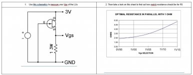
Matching R5 and Q1
Looking for confirmation if I did this right or not:
I tried measuring the Vgs using the circuit in image below and then choosing R5 based on the chart, but taking the Vgs measurement was difficult for be because the it was constantly changing with the jfet temperature. So I took my best guess at the Vgs value before the jfet got too hot and selected R5 from the chart. This didn't work well at all, my voltage at the drain of Q1 was ~2.7V (should be ~3.5).
So this is what I did (and am looking for confirmation on). I built up the amp, and put a 10ohm 5W potentiometer in place of R5 with the initial resistance set per Vgs and the chart below. P1 and P2 set to mid position by counting turns. After approximately 5 minutes after power up begin to periodically adjust P1 and the "R5" potentiometer as the amp warms up to keep the voltages at Q1 drain and R9-C1 junction at the values on the F3 schematic (3.5V and 21V respectively). Let the amp run for 1 hour make final adjustments. Remove "R5" potentiometer and measure resistance. Solder in real resistor for R5 of closest value I could make up from resistors on hand.
This worked well to obtain the voltage values on the schematic is there anything I am missing with this approach?
Thanks,
Chas
Attachments
Last edited:
I have Papa's LUs with WG45 measurements. My JFets have 1.2V VGS: according to Jeff's table I'd chose 7 ohm circa (in parallel with 1 Ohm), right?
That is what the chart suggests, my luck wasn't the best just using the chart hence the temporary "R5" potentiometer. I just used the chart as a starting point.
Interesting new line from Claritycap (up to 600uF) for those who don't need full bass extension (biamp):
https://www.hificollective.co.uk/sites/default/files/2021-08/clarity-cap-tc-datasheet.pdf
https://www.hificollective.co.uk/sites/default/files/2021-08/clarity-cap-tc-datasheet.pdf
Maybe re-badged DC-Link capacitors ? 😀
DC-LINK Capacitors / Intermediate Circuit Capacitors - WIMA – Competence in Capacitors
WIMA is only an example, lots of manufacturers make DC-Link MKPs now ...
Regards, Claas
DC-LINK Capacitors / Intermediate Circuit Capacitors - WIMA – Competence in Capacitors
WIMA is only an example, lots of manufacturers make DC-Link MKPs now ...
Regards, Claas
even when it is revealed origin of Audiophool caps, they claim as they're custom made by their specifications
oh yeah!!!!
oh yeah!!!!
Well, there's also Epcos, Vishay, Kemet ... if you shop around a bit and are not in a hurry, you can find some amazing bargains, as these are now standard industrial items on power electronics like industrial SMPS or power inverters.
I paid 38 EUR for two boxes with 27 caps each of these, surplus ...
I've built the B+ power supply for my EL84PP tube amp by paralleling a few of this type of caps for each channel ...
I paid 38 EUR for two boxes with 27 caps each of these, surplus ...
I've built the B+ power supply for my EL84PP tube amp by paralleling a few of this type of caps for each channel ...
Attachments

Speaking of DC-link caps:
I ordered these for application in a high-voltage CLC power supply for an upcoming tube front end. They don't seem excessively expensive, given their automotive environmental rating.
https://www.mouser.com/ProductDetai...9lf6KwQ9bHw==&countrycode=US¤cycode=USD
I will eventually be reporting results in the VFET builders thread.
Well, there's also Epcos, Vishay, Kemet ... if you shop around a bit and are not in a hurry, you can find some amazing bargains, as these are now standard industrial items on power electronics like industrial SMPS or power inverters.
I paid 38 EUR for two boxes with 27 caps each of these, surplus ...
I've built the B+ power supply for my EL84PP tube amp by paralleling a few of this type of caps for each channel ...
you, Lucky Predator Bstrd

- Home
- Amplifiers
- Pass Labs
- F3 Builders Thread