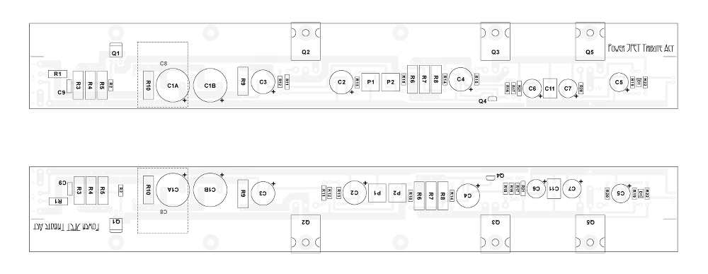
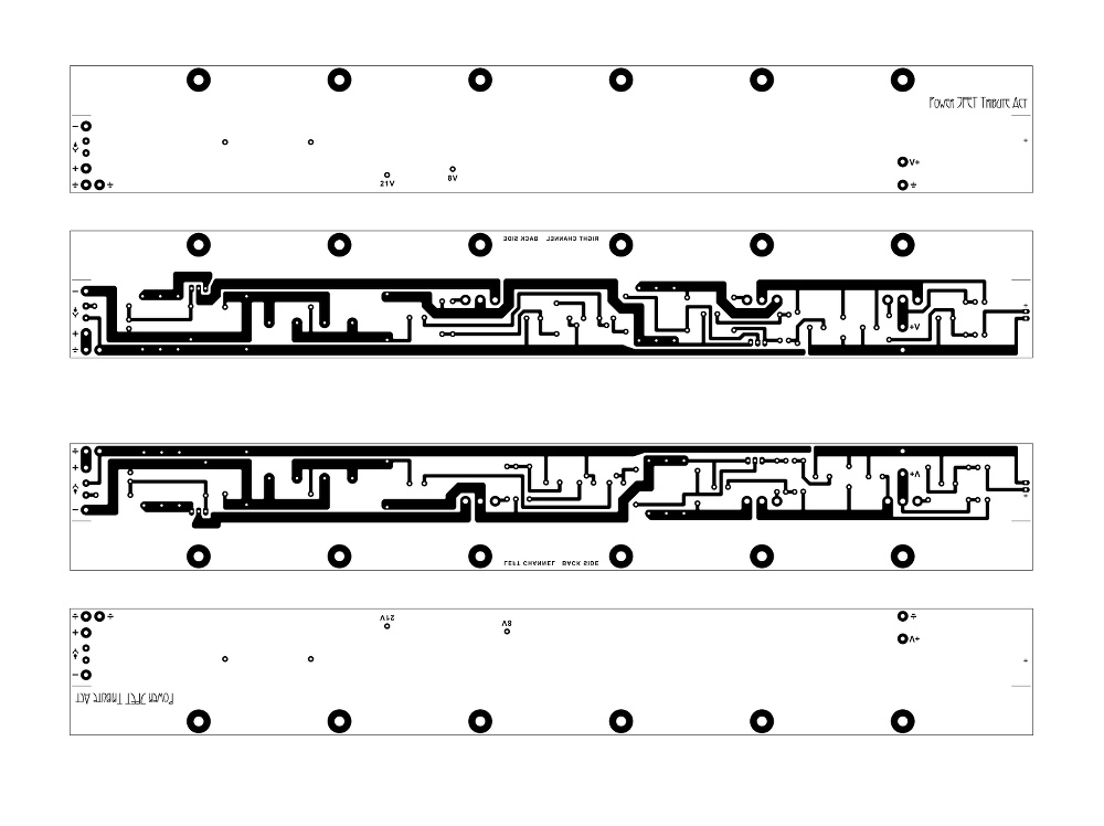
I think (hope?) I'm getting near my final board layout.
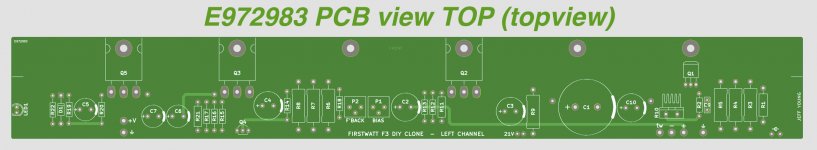
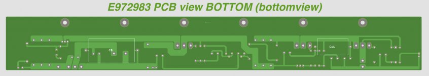
I've changed the output caps since the big Panasonics are NLA: I'm using a pair of Wurth 8200uF electrolytics and a Mundorf 8.2uF polypropylene jelly roll.
I've also added a film cap (6.8uF polyester) to the Cmultiplier output.
I've changed the output caps since the big Panasonics are NLA: I'm using a pair of Wurth 8200uF electrolytics and a Mundorf 8.2uF polypropylene jelly roll.
I've also added a film cap (6.8uF polyester) to the Cmultiplier output.
Attachments


Discussion over on the DEF amp thread regarding protecting JFETs with zeners has led me to try and understand the F3 a bit better.
As I understand it, an N-channel JFET is a normally-on device which can be turned off by applying a negative voltage potential between its G and S. In the case of the LU1014, -1V should give a fully-off state.
The LU1014 spec also says "Device fully ON with Vgs = 0.7V", suggesting that a bit of positive bias is OK. So I guess fully open to fully closed is a Vgs of +0.7 to -1V. (Unless that positive bias part isn't linear, in which case we'd still want +0 to -1V.)
The F3 holds the LU1014's S at +1.1V. Its G is fed over a 9.1K/47.5K voltage divider, which should give 0.84Vin, or +1.2 to -1.2V for a consumer-level +1.4 to -1.4V signal.
That gives us a Vgs of +0.1 to -2.3V, which doesn't seem to fit with my calculated on/off range. What am I missing?
Yikes. I haven't a clue what to do with that.
Let me try and make a stab at it. The feedback is out of phase, right? Which means it will compress the input waveform? So with, for instance, 50% feedback we might expect a +/-1.2V signal to go to +/-0.6V?
(Feedback is usually measured in dB. How does that correlate to my 50% figure?)
I've either got the wrong end of the stick, or I'm missing something else. Even with 50% feedback (which I doubt), that +/-0.6V signal will give us a Vgs from -0.5 to -1.7V, which still descends well below the pinch-off Vgs.
My head hurts....
for proper analysis "all" you need is calculus of OLG (open loop gain) then it's easy going backwards , to determine either feedback (amount ) or CLG (closed loop gain)
moi being lazy to calc now ...... or even fire up LTSpice and search for all necessary thingies
moi being lazy to calc now ...... or even fire up LTSpice and search for all necessary thingies
roughly ....... for 1W/8R at output , you need 2V6pp at input
LU sees 210mVpp between gate and source
that , by mu crude LTSpice sim
LU sees 210mVpp between gate and source
that , by mu crude LTSpice sim
I've been practicing my toner transfer and etching skills. While I've learned a lot, one of the things I've learned is that I don't enjoy toner transfer or etching. 🙄
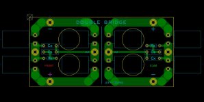
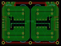
So it's back to the drawing board to produce Gerbers for a fab house. I did up a board for a pair of bridge rectifiers (with snubbers) that is currently with EuroCircuits, and I have a first draft for a dual mono PSU.
I did both those sans schematic, but KiCAD appears to work more efficiently from a schematic, so I've also done a first-draft schematic for the left channel.
Comments welcome.
Attachments
Ask DIY Chip Amplifier Kits, PCB's, Components and Information.I'm interested into F3, any idea where can I buy the F3 pcb?
Checked but didn't find any FE PCB for sale.
Hi Moppy,
I made 3 sets of my boards, and I only need 2.
There are a few changes from the FirstWatt versions:
1) added an optional film capacitor after the c-multiplier
2) changed C1 to a Mundorf MLytic AG (the Panasonics are no longer available)
3) changed R5 to a TO package
4) added a pre-capacitor tweeter output
5) separated power and signal grounds
6) made room for the larger Elna Silmic IIs for C2, C3, C4 and C10
... but you might want to wait so I can make sure they work first. 😉
Cheers,
Jeff.
I know but he may have boards. Just ask.Checked but didn't find any FE PCB for sale.
Well, that's interesting. Hours after posting here the UPS man arrived with my left and right channel boards. EuroCircuits sent out 4 instead of 3. (Is it normal for them to send extras? This is only my second order from them, but the first one didn't have any extras.)
Anyway, assuming they check out this means I could have two sets available....
Anyway, assuming they check out this means I could have two sets available....
I'm interested in buying one set, if you make sure they work. Can you post pics.Well, that's interesting. Hours after posting here the UPS man arrived with my left and right channel boards. EuroCircuits sent out 4 instead of 3. (Is it normal for them to send extras? This is only my second order from them, but the first one didn't have any extras.)
Anyway, assuming they check out this means I could have two sets available....
There are pre-production pictures a page or so back in this thread (post #590). I'll take some pictures of the real things in a day or so.
One thing to note: these are made for FirstWatt-style cases. They're 14" long with heatsink holes every 2". They are not the "UMS" hole-spacing for the DIYAudioStore cases.
I'll put El Reino down for the second set. Are you in any great hurry? I'm still waiting on a transformer from Toroidy as the one I have on hand is a bit smaller than I'd like....
Cheers,
Jeff.
No hurry, thank's🙂There are pre-production pictures a page or so back in this thread (post #590). I'll take some pictures of the real things in a day or so.
One thing to note: these are made for FirstWatt-style cases. They're 14" long with heatsink holes every 2". They are not the "UMS" hole-spacing for the DIYAudioStore cases.
I'll put El Reino down for the second set. Are you in any great hurry? I'm still waiting on a transformer from Toroidy as the one I have on hand is a bit smaller than I'd like....
Cheers,
Jeff.
- Home
- Amplifiers
- Pass Labs
- F3 Builders Thread