Ermm... Pardon me if I am wrong. I think the documentation (OM)doesnt state how F3 works like how you describe in F5 (after the actual working circuit area).
I think Zen V9's documentation is close though.
You have one detailed F3 document for the babies?
😀
I think Zen V9's documentation is close though.
You have one detailed F3 document for the babies?
😀
toufu said:How should P1 or P2 be adjusted? Thanks!
I believe that it is just enough to set up recommended voltages by P1 and P2. If your idea is to fight against THD by fine tuning the P1 and P2, it is not noteworthy to my opinion. Major contributions to sound make power supply and parts quality, especially the output capacitor and coupling capacitor in the modulated current source.
I'm not sure, I got mine from the first burning amp event.
Maybe Mr. Pass could tell us where he got them?
Maybe Mr. Pass could tell us where he got them?
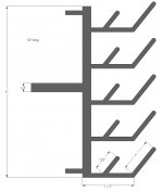
grubyhalo said:Is this heat-sink available anywhere?
It is my proprietary extrusion.
😎
Case and Heat Sinks
I was in a group buy for case and heat sinks for my future F3 and it crashed and burned. Now I am starting from scratch.
Any Suggestions?
I was in a group buy for case and heat sinks for my future F3 and it crashed and burned. Now I am starting from scratch.
Any Suggestions?
Re: Case and Heat Sinks
That doesn't sound suprising.
I normally get aluminum sheet in 24" and 48" lengths and cut it to length with a non-ferrous table-saw blade.
With the F3, I am having speedymetals.com do the cutting, since I can't seem to cut a strait line that good.
Using PD boards with Fets directly attached to a Conrad heatsink, the fets run 65C and I dont want that to go too much higher.
I have used Barred Boss ebay Heatsinks, previously, and find them to dissapate heat well. Other than that, I go surplus.
tbrooke said:I was in a group buy for case and heat sinks for my future F3 and it crashed and burned. Now I am starting from scratch.
Any Suggestions?
That doesn't sound suprising.
I normally get aluminum sheet in 24" and 48" lengths and cut it to length with a non-ferrous table-saw blade.
With the F3, I am having speedymetals.com do the cutting, since I can't seem to cut a strait line that good.
Using PD boards with Fets directly attached to a Conrad heatsink, the fets run 65C and I dont want that to go too much higher.
I have used Barred Boss ebay Heatsinks, previously, and find them to dissapate heat well. Other than that, I go surplus.
Hi All,
Need your advice. I too am looking into building the F3.
Am a little confuse with the power supply design. In the
schematics I see only 1 hook-up point. Are the voltages
sum together or ?
Thank You
Need your advice. I too am looking into building the F3.
Am a little confuse with the power supply design. In the
schematics I see only 1 hook-up point. Are the voltages
sum together or ?
Thank You
JC951t said:Hi All,
Need your advice. I too am looking into building the F3.
Am a little confuse with the power supply design. In the
schematics I see only 1 hook-up point. Are the voltages
sum together or ?
Thank You
If you use a dual rail (V+/V-) power supply, then yes, tie V+ and V- together to get 48v+.
If you use a dual single rail design, then you need 36v secondaries. This is what I did, but only because I got a good deal on the transformer
😀
JC951t said:Hi Tea Bag,
Thanks for the advice. Is there any advantage using the
original design ?
Well, thats what nelson does, and it also also allows you to use less 50 or 63v capacitors.
I believe it does have some other capacitance changes, but I don't recall what they are.
JC951t said:Hi Tea Bag,
Thanks for the advice. Is there any advantage using the
original design ?
Tea-Bag said:
Well, thats what nelson does, and it also also allows you to use less 50 or 63v capacitors.
I believe it does have some other capacitance changes, but I don't recall what they are.
Papa made generic First Watt PSU , which allows use of 15000uF/25V Pana caps ( presume that he owns truckload of them ) in both configurations - bipolar voltage ( say +/-24Vdc ) and monopolar ( stacked +/-24 ,which gives +48Vdc) .
there is no special benefit of that , except Papa's clever use of resources .
Does anyone have the F3 supply diagram? The service manual doesn't seem to be correct and has the normal Fx series supply.
Thank you, (and I searched)
Chris
Thank you, (and I searched)
Chris
The power supply diagram in the service manual is absolutely correct. Two stacked 24V rails = 48V.
- Home
- Amplifiers
- Pass Labs
- F3 Builders Thread