LU1014's in the UK
Hi - I have ordered 10 of these and they are on their way (from Singapore) - obviously I will not need all of them so when they arrive I will let you know and if you are still without then I can let you have a couple.
Alan
themystical said:Anybody have a couple of LU1014's in the UK for my F3 Build?
Hi - I have ordered 10 of these and they are on their way (from Singapore) - obviously I will not need all of them so when they arrive I will let you know and if you are still without then I can let you have a couple.
Alan
Re: four F5 pls
Peter,
I got them today, so fast!
great quality thanks
regards,
Evan
chatziva said:Peter
Can you email me a paypal request for 4 off F5 boards please ?
As for shipping costs, I am in the UK.
Thanks
Evan
Peter,
I got them today, so fast!
great quality thanks
regards,
Evan
I am building a pair of SE Mono F4's and would like opinions.
I have 2 pair of the Conrad Heatsinks from the group buy.
Would mounting 3 Mosfets per heatsink and running a higher bias current to get 50 deg C be better than all 6 Mosfets on 1 heatsink at a lower current?
What bias current would each allow for.
rigma
I have 2 pair of the Conrad Heatsinks from the group buy.
Would mounting 3 Mosfets per heatsink and running a higher bias current to get 50 deg C be better than all 6 Mosfets on 1 heatsink at a lower current?
What bias current would each allow for.
rigma
will other cap than P6577-ND CAPACITOR 15000UF 25V ELEC TSHA works better on this AMP?
i want to order 2 brands/models to test the diference!
i want to order 2 brands/models to test the diference!
F5
I receive your board Peter, Excellent boards !
Can you tell us what resistor you use in F5 boards ?
Thank you
Peter Daniel said:Yesterday I installed Caddocks MK132 in place of Mills feedback resistors. I used 4 x 150R per board, which gives slightly more gain. The sound seems to be less forward and maybe a bit better bass, but nothing really major.
I receive your board Peter, Excellent boards !
Can you tell us what resistor you use in F5 boards ?
Thank you
F5 BOM check
Peter,
Just starting to put the F5 boards together and noticed that the BOM does not include any small caps for the psu board and checking your photo it seems that you do not populate them. So is it just the four large caps plus either 4 or 8 resistors (for 5W or 3W versions) on the psu?
Thanks
Alan
vonfilm said:Peter,
Are the parts in red on the second attachment an update or correction?
Those are update to the original circuit. Nelson changed it later on. These values will work more better.
Re: F5 BOM check
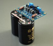
Indeed, there are no small caps on the amp board, and I don't see a need for any additional bypasses, but I mount my electrolytics directly on amp board 😉
The picture also shows what resistors I'm presently using.
AlanElsdon said:Just starting to put the F5 boards together and noticed that the BOM does not include any small caps for the psu board and checking your photo it seems that you do not populate them. So is it just the four large caps plus either 4 or 8 resistors (for 5W or 3W versions) on the psu?
Indeed, there are no small caps on the amp board, and I don't see a need for any additional bypasses, but I mount my electrolytics directly on amp board 😉
The picture also shows what resistors I'm presently using.
Attachments
Peter,
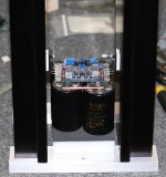
So two capacitors per channel - what look like Caddocks, Mills and Rikens resistors, but.... how do you attach the output devices to the heatsink - it seems that they must be mounted near the edge of the heatsink.?
So is there anything left on the capacitor board?
Would you be using the copper bar then as your star-ground?
Alan
just missed your second post
Peter,
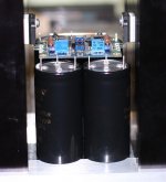
So that is one channel? If so then I take it the caps at the back are also attached to that one board?
Yet again it looks like a work of art in the making.
Alan
Peter,
So that is one channel? If so then I take it the caps at the back are also attached to that one board?
Yet again it looks like a work of art in the making.
Alan
- Status
- Not open for further replies.
- Home
- Group Buys
- F3 and F4 Clone PCB Reissue group buy, also F5 PCBs