Hi Everyone,
Well my EZDAC has burned in about eight hours so I gave my it a good listen tonight. Very nice, very real sounding, great clarity, with a very spacious sound, solid base also, it has opened up and improved since I first heard it. Kudos to Evan on a great design.
I did try the zener mod after my listening session, it didn't work no sound only a little high pitched whine. Luckily when I removed the zeners everything was fine and the DAC was singing again.
PJN
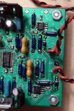
Attachments
Hi Ray,
I used the ones specified in the 1.5 BOM
1N5314 Central Semiconductor Current Regulator Diodes
PJN
I used the ones specified in the 1.5 BOM
1N5314 Central Semiconductor Current Regulator Diodes
PJN
No they were out of stock so I used the substitute specified in the BOM a
LME49710.
http://cache.national.com/ds/LM/LME49710.pdf
PJN
LME49710.
http://cache.national.com/ds/LM/LME49710.pdf
PJN
The high pitch whine indicates oscillation, maybe this type doesn't like the CRD at it's output. You can try with a passive version, a resistor, and then move up to a FET and see what it does (see link from earlier post).
Ray
Ray
Hi Ray,
Thanks for the info, I think that I'll try installing another PSU and separate the digital and analog stages first. I do have a couple of questions though.
U9 And U10 both feed off of the positive rail, would using a dual PSU like this one Low Current Dual Power Supply (LCDPS) - A Dual Regulated CLRC Supply make sense ? I wouldn't need a negative rail since I could leave U8 and U11 on the original bipolar supply, cut the jumpers between V1, V2, and V3, and feed U9 and U10 separately off the new PSU.
My second question is where would I hook the gnd from the new PSU to ? Just to the common ground plane like at G4 for example ?
PJN
Hi all
Some news after such a long time... 😉
I've just finished soldering my EZDual, and it works fine +15.1v and -15.3v.
I'll let you know for the DAC, mostly populated, not connected yet.
I've' to check twice or more before pluging.
Do you have some tips ?
Cheers 😎
Some news after such a long time... 😉
I've just finished soldering my EZDual, and it works fine +15.1v and -15.3v.
I'll let you know for the DAC, mostly populated, not connected yet.
I've' to check twice or more before pluging.
Do you have some tips ?
Cheers 😎
Hi Paul,
That dual PSU is perfect for the ezDAC. I would set both sections to 9V and use it to supply U8 and U9 (the digital section) through V1 and V2, and connect U10 and U11 to the ezDual (not U8 and U11 as you mentioned). This way, the analog and digital sections are separated.
Remove the two jumpers, and connect ezDual's positive output to V3. You should use G1 for the new PSU ground and G4 for the existing ezDual.
Regards,
Ray
Hi all
Some news after such a long time... 😉
I've just finished soldering my EZDual, and it works fine +15.1v and -15.3v.
I'll let you know for the DAC, mostly populated, not connected yet.
I've' to check twice or more before pluging.
Do you have some tips ?
Cheers 😎
I'd power up the ezDAC board with an adjustable bench supply if possible. I used one with current limiting as well, so nothing gets fried in case of a soldering short. And I used a magnifying glass to check the fine-pitched SMD's 😀.
Ray
Ah, that diode mod. Those aren't zeners, by the way, they're current regulators.Hi Everyone,
...
I did try the zener mod after my listening session, it didn't work no sound only a little high pitched whine. Luckily when I removed the zeners everything was fine and the DAC was singing again.
PJN
I doubt you'd hear a difference with the 49710 anyway.
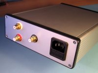
I finally got around to wiring up my ezdac. I always dread having to drill out and file an IEC power inlet. I used double sided sticky tape to mount the ezdual (for now). The Lansing case I picked for it has a vinyl coating on it (so my ezdual should be safe).
I've got to power it up and test it now. I know I'll have the right voltages out of the ezdual.
I've got to power it up and test it now. I know I'll have the right voltages out of the ezdual.
Yes, that's absolutely one of the most annoying things to do  . I always do it first, to get it over with. I usually mount them from the back so the hole isn't covered, but last time I used a few snap-in units, with integrated fuse. They are very easy to mount and the hole is a simple rectangle. The edges don't have to be that straight because the inlet covers it 😀.
Fingers crossed...
Ray
. I always do it first, to get it over with. I usually mount them from the back so the hole isn't covered, but last time I used a few snap-in units, with integrated fuse. They are very easy to mount and the hole is a simple rectangle. The edges don't have to be that straight because the inlet covers it 😀.Fingers crossed...
Ray
Differential Signal Traces/wiring
Reviewing the attached notes on "Differential Signals" and their paths (traces), I now see a preference (real or imaginary here?) to maintain the receiver OPAmp on the EZDac board, rather than bringing it out to a companion board with the Headphone Amp. I was hoping to use of some of the AD712 OPAmps I have on hand (not SM frames).
http://www.ultracad.com/articles/differentialrules.pdf
Anyone here do the "off board" receiver mount? .... any EMI pickup problems?
Louis
Hi All,
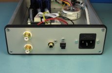
I finally got around to installing a second PSU to separate the digital and analog sections. And while was at it I also installed a TOSLINK optical input module. Ao I can input either optical or coax by fliping a switch.
The extra PSU did make a noticible difference for the better. The DAC seems to have more depth, detail, and dynamics. Very nice.
PJN
Anyone here do the "off board" receiver mount? .... any EMI pickup problems?
Louis
No, not me Louis, I use the on-board opamps. I can imagine doing the I/V-conversion closest to the DAC gives best results, but it would be even better to use separate opamps for both current outputs, and do the summing with a third (or use an other solution for that, maybe discrete). But the DAC outputs are current-out into a low impedance (I/V resistor or something like a virtual opamp ground if you use off-board solution), so noise and other disturbances have a limited effect on this.
Hi All,
I finally got around to installing a second PSU to separate the digital and analog sections. And while was at it I also installed a TOSLINK optical input module. Ao I can input either optical or coax by fliping a switch.
The extra PSU did make a noticible difference for the better. The DAC seems to have more depth, detail, and dynamics. Very nice.
PJN
That's great, I also noticed improvement doing this. It reduces digital noise entering the analog section. You should also try the luxury version with separate discrete regulators for each supply 😀.
Ray
Last edited:
- Status
- Not open for further replies.
- Home
- Source & Line
- Digital Line Level
- ezDAC v.1.5 Builders Thread