Hi Ray,
You were right, I had a bad joint on F2, I fixed it and I am getting 3.3v on pin 4 Vdd and 0.73v on pin 3. But unfortunately still not singing.
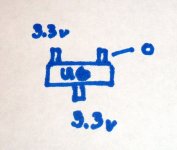
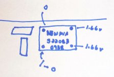
I checked voltages around U6 and the pulse transformer they are shown in the pics attached.
PJN
You were right, I had a bad joint on F2, I fixed it and I am getting 3.3v on pin 4 Vdd and 0.73v on pin 3. But unfortunately still not singing.
I checked voltages around U6 and the pulse transformer they are shown in the pics attached.
PJN
Attachments
Looks o.k. to me. How did you attach the S/P-dif signal, did you connect ground of the coax to J0 and signal to J1?
Ray
Ray
Hi Ray,
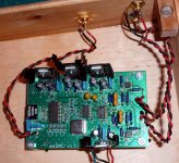
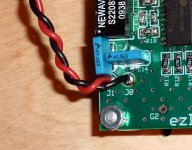
Yes I did and I verified that the digital source was working correctly by trying it on my other system. Here are some pics of my hookups. I also checked the rca's back to the board for continuity they were all fine.
PJN
Yes I did and I verified that the digital source was working correctly by trying it on my other system. Here are some pics of my hookups. I also checked the rca's back to the board for continuity they were all fine.
PJN
Attachments
Well, I think for further investigation you need a scope, to verify the digital signals between the three chips. It could be something tiny like a resistor or cap in the 8416 PLL circuit, or around the other chips that's causing the problem. A good DMM with frequency measurement capabilities would also work. Then you can verify the bitclock and wordclock signals.
Regards,
Ray
Regards,
Ray
Hi Ray,
Thanks for the help. Since I don't have a scope or want to buy one I guess I'll spend some time double checking all of the smds. If I can't get it working I'll consider this project as experience gained and use whatever parts I can for future projects.
PJN
Thanks for the help. Since I don't have a scope or want to buy one I guess I'll spend some time double checking all of the smds. If I can't get it working I'll consider this project as experience gained and use whatever parts I can for future projects.
PJN
Ok, I hope you can find something. Maybe there's a fellow-DIY'er in your neighbourhood that can check it with a scope for you? As an alternative, you could send the ezDAC board to me and i'll check it for you. It will cost you some shipping, that's all. I'd hate to see your ezDAC project strand like this...
Ray
Ray
Ray,
Thanks so much for your kind offer. A little shipping would be a small price to pay considering all the time I've invested in this project so far. I'll give it one more going over this week to see if I've missed anything obvious. If I can't get it going I'll email you privately for mailing directions.
PJN
PJN, sorry for saying that, but your soldering looks very messi.
I think you should accept Ray's offer. This was my idea too, to help you
bring this project to a sucsessful end.
All SMD have to be tied up. May be something is toasted or shorted.
Without a scope I guess you have no chance to bring it up to live.
Let me know if I can do something.
regards Michael
I think you should accept Ray's offer. This was my idea too, to help you
bring this project to a sucsessful end.
All SMD have to be tied up. May be something is toasted or shorted.
Without a scope I guess you have no chance to bring it up to live.
Let me know if I can do something.
regards Michael
Mikel_ann,
I agree with you, my soldering is messy, this was my first experience with using SMD parts. My eyes aren't what they used to be and I found working with such tiny parts challenging. I will be taking up Ray on his kind offer after I give it one last try.
PJN
I agree with you, my soldering is messy, this was my first experience with using SMD parts. My eyes aren't what they used to be and I found working with such tiny parts challenging. I will be taking up Ray on his kind offer after I give it one last try.
PJN
Hi PJN, try to find a 35mm wideangele lense upside down or a
a lense from a slide projector to check and solder.
I put some on my table lamp for doing this job.
Try that, it works fine.
For soldeing you need a sharp soldering tip and only a very little bit tin.
You can use Collophium (from pharmacy) dissolved in alcohol as flux or
"solder honey". Check Youtube for soldering SMD.
With a small brush you can brush the flux on the board an on the legs.
Take some old Computer boards and try to remove parts an back again.
For removing an "heatgun" is useful. (like a hairdryer, but hot if this translation is wrong)
Its not an easy job, but possible.
regards michael
Ray,
Thanks so much for your kind offer. A little shipping would be a small price to pay considering all the time I've invested in this project so far. I'll give it one more going over this week to see if I've missed anything obvious. If I can't get it going I'll email you privately for mailing directions.
PJN
No problem, it is not too difficult for me to check a board like this, since i've already built a few. Just let me know when you are done with it, and i'll be happy to take a look at it.
Ray
Mikel_ann,
I agree with you, my soldering is messy, this was my first experience with using SMD parts. My eyes aren't what they used to be and I found working with such tiny parts challenging. I will be taking up Ray on his kind offer after I give it one last try.
PJN
I feel your pain. I failed at least three times trying to build my last ezDAC. Then I tried using the toaster oven method, and I got it to work the first time. I haven't touched my ezDAC since then, and haven't tried to build another one. 😀
I've found that as long as the lead spacing on ICs is 0.5mm or larger, I can solder by hand with a fine tip on a Metcal or similar soldering system and using very fine solder. If you bridge a couple pins you can fix with solder wick. The best thing to do is to solder diagonally opposite corner pins and once the device is located properly (and legs not floating off the board in solder) to solder down the othe two diagonals. Then solder the rest of the pins.
I find using strong magnification essential; more is needed now than 15 years ago, but even then fine pitch stuff is next to impossible to do with the naked eye.
I find using strong magnification essential; more is needed now than 15 years ago, but even then fine pitch stuff is next to impossible to do with the naked eye.
Update on mt EZDAC 1.5
Hi all,
I did take Ray up on his kind and generous offer to take a look at my board and he was able to get it singing in no time. He discovered that I had screwed up one of the pads on a cap feeding the reciever and had a loose pad on the reciever. Thank you Ray, I could have never found those faults myself.
So now there is one more EZDAC in the world. My build is the bog standard, single PSU. But so far my impressions have been very favorable. It easily sounds significantly better than the modified DVD player it is replacing. Much more relaxed with very good imaging and detail. I'll let it burn in for a few days and try to do a head comparison against the opus DAC from twisted pear audio that I built last year. They have very similar features. Next moves will be to add a separate PSU to separate the digital and analog sections, and add CRDL and CRDR. I'll report back with my impressions of these changes.
PJN
Cool! I definitely am interested to hear about the addition of the diodes. I don't think anyone has implemented those yet.
...So now there is one more EZDAC in the world...
That's good news! I guess it survived the trip across the ocean 😀
Ray
Hi PJN glad to hear that. 
Have fun with it. I had a chordette gem here for a few days and
found the ezDac has a lot more detail.
regards Mikel
Have fun with it. I had a chordette gem here for a few days and
found the ezDac has a lot more detail.
regards Mikel
Hi Ray,
It made it back over the pond in one peice, it was delivered this past Friday. I think it may well be the most extensively traveled EZDAC out there.
Evan,
I have the diodes in my parts bin so I think I'll pop them in first, before the additional PSU. First I want to get a good handle on the unmodified DAC's performance so that I can tell if there is a difference.
PJN
Diodes mod? Is this from earlier in the thread and I missed it?Cool! I definitely am interested to hear about the addition of the diodes. I don't think anyone has implemented those yet.
It took almost two weeks then. That's amazing, considering the fact that they indicate 4 to 8 working days... But it's singing now! 😀
Ray
Ray
- Status
- Not open for further replies.
- Home
- Source & Line
- Digital Line Level
- ezDAC v.1.5 Builders Thread