That's a good news, Sander. 5° of phase margin at the point where loopgain falls to 0dB is definitely not enough, it indicates to almost oscillating system. It seems it was stabilized only due to that drastic slew rate limitation by 10R + 1nF compensation.
However, though there is an improvement, I assume we might like to see more than 20° of phase margin.
However, though there is an improvement, I assume we might like to see more than 20° of phase margin.
Last edited:
Thanks for the input, PMA. Many do not understand that it is the RISETIME of the signal that causes the tendency for slew rate limiting and TIM in general. The height of any particular audio frequency is secondary and that many audio sources will push against the maximum rise-time envelope on a regular basis.
Regarding high frequencies >10kHz, some recordings have very high content of frequencies about 10kHz and above 10kHz.
Pavel why not plot a distribution of rate of change directly, the FFT carries neither this nor crest factor information? I have done extensive studies with xDSL/multitone signals and the results are interesting.
many audio sources will push against the maximum rise-time envelope on a regular basis.
With op-amps with 100's of V/us of slew rate routinely available now you will eventually have to give up on this line of reasoning.
John . . . I cannot think of one modern OP amp for audio that has a slew rate problem. Not one.
I think Sander was inspecting OLG, not LG..
Yes indeed, my mistake, here's the closed loop gain plots:
Original ExtremA:

ExtremA with proposed part value changes:

For the original ExtremA phase shift is 155 degrees, so 25 degrees of phase margin is left. For the ExtremA with the proposed changes the phase shift is 144 degrees, which leaves 36 degrees of phase margin, which is a lot healthier.
Thoughts?
Unrealistic conditions give poor results for most of the critical fidelity sound for someone more measurements.
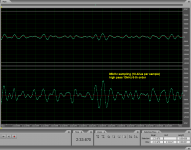
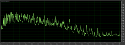
Just one single example will disprove your point. See attached, a Windchime recording on SACD.
You mix up the average music energy which indeed is low at high frequencies, with the fact that full scale peaks can and do occur at 20kHz and above. So your equipment must be able to reproduce full-scale 20+kHz signals, even if they occur not constantly.
Sorry Sander, had to make the point.
Jan
Attachments
Thanks for the input, PMA. Many do not understand that it is the RISETIME of the signal that causes the tendency for slew rate limiting and TIM in general. The height of any particular audio frequency is secondary and that many audio sources will push against the maximum rise-time envelope on a regular basis.
I'm sure you understand that rise time and slew rate are two different things.
Rise time is a small signal parameter - you can have a rise time of 2 uS and still be slew rate limited (which is a large signal parameter). Or not.
Jan
Regarding high frequencies >10kHz, some recordings have very high content of frequencies about 10kHz and above 10kHz.
Pavel why not plot a distribution of rate of change directly, the FFT carries neither this nor crest factor information? I have done extensive studies with xDSL/multitone signals and the results are interesting.
The content of high frequencies does not mean that it should be a high rate of change.
Only the knowledge of the voltage gives a comprehensive picture of the need for speed.
Yes indeed, my mistake, here's the closed loop gain plots:
Thoughts?
Sander, it seems you are confusing the issue or us 🙂
Loop gain plots are the key to understanding stability. Please check
www.ti.com/lit/ml/sloa077/sloa077.pdf
chapter 5.5
To explore loopgain, open the FB loop, put the voltage source from output to the FB resistor and plot V(out)/-V(A), where A is the second node of the voltage source. You might like to search for Middlebrook stability method, general feedback theorem
General Feedback Theorem (GFT) explained
Neither open loop gain nor closed loop gain help.
The content of high frequencies does not mean that it should be a high rate of change.
Only the knowledge of the voltage gives a comprehensive picture of the need for speed.
I have posted a time domain record (not only FFT) with 96kHz sampling rate, you can read dv/dt directly and multiple it to get output SR at the amplifier output. Your suggestion that 1.6V/us is enough for a 100W/8 ohm amplifier is a nonsense. Even 10V/us that ExtremA measured is very low. You are also forgetting that low SR affects bad TIM/SID behavior and CCIF 19 + 20 kHz distortion.
My time record plot shows 30% full scale peak - to - peak swing step within 2 samples of 96kHz frequency.
full scale peaks can and do occur at 20kHz and above. So your equipment must be able to reproduce full-scale 20+kHz signals, even if they occur not constantly.
Sorry Sander, had to make the point.
Jan
Exactly.
Just one single example will disprove your point. See attached, a Windchime recording on SACD.
You mix up the average music energy which indeed is low at high frequencies, with the fact that full scale peaks can and do occur at 20kHz and above. So your equipment must be able to reproduce full-scale 20+kHz signals, even if they occur not constantly.
Sorry Sander, had to make the point.
Jan
SACD 1bit converter
for 5Hz has 2,8MHz / 5Hz / 4 = ±140000 levels
for 100Hz has 2,8MHz / 100Hz / 4 = ±7000 levels
for 100kHz has 2,8MHz / 100kHz / 4 = ±7 levels
Levels of voltage can not be the same.
SACD 1bit converter
for 5Hz has 2,8MHz / 5Hz / 4 = ±140000 levels
for 100Hz has 2,8MHz / 100Hz / 4 = ±7000 levels
for 100kHz has 2,8MHz / 100kHz / 4 = ±7 levels
Levels of voltage can not be the same.
This is utter nonsense. The one bit is successive, not starting from zero.
SACD is perfectly happy to encode/decode 20kHz at full scale.
I showed you a recording with high levels of high freq. Saying it cannot be in the face of reality is pretty stupid in my book.
jan
- Status
- Not open for further replies.
- Home
- Amplifiers
- Solid State
- ExtremA, class-A strikes back?