Has anyone tried making the interior rear wall of a speaker box strongly ‘convex’ from top to bottom to disperse internal reflections. I’ll try it one day as it’s feasible with a small full range driver. Would it help though?
If the convex (or whatever shapes) are similar or larger than the wavelength of the frequency that you want to "treat", there is a chance that it will work. Usually the standing waves (modes) in a loudspeaker box are at low frequencies, and their wavelengths correspond to the enclosure dimensions. So whatever "shapes" you put in the box, they will be smaller than the enclosure, so the "shapes" will be too small to have a large effect.
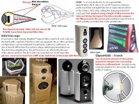
A sphere cabinet shape has several SPL resonances. B&W added a rear tapered tube stuffed with absorption material. French Elipson 4260 uses a midrange sphere cabinet, BUT adds a rear resonant chamber to remove the 3D equal paths resonances of a sphere.
It is best to design cabinets which reduce resonances, and then add absorption material like B&W.
It is best to design cabinets which reduce resonances, and then add absorption material like B&W.
Attachments
When I design a speaker like a horn or TL in Akabak, if there is a bad resonance peak that just can’t be removed with other means, I often add a stub to remove the peak. It is easy to do and try out computationally in Akabak. Basically take your peak frequency you want to squash and calculate the 1/4-wave length. Make a TL stub (closed end pipe) of that length and stuff it with fiberglass. Adjust stuffing to flatten the offending peak. It is very effective and you don’t need a very large cross sectional area (CSA) stub. Alternatively, take a PVC pipe of some diameter and cut to length and cap off one end. You can use elbows to fold it. Will need a big pipe though like 2in to 4in dia. It gets bulky this way. Stubs built into cabinet are sleeker and easier I think.
So for example if your TL or born has a bad peak at say 170Hz, take inverse of frequency and multiply by 342m/sec for speed of sound and divide by 4 for quarter wave length. You get 50cm. You can fold that to a 25cm long line and about 2cm to 2.5cm deep x width of cabinet. Put the opening of that TL near where the driver is.
Adjust stuffing density to taste. It’s quite simple.
In Akabak, you can test to see what kind of CSA you need.
Last edited:
The 1/4 wave absorber makes sense. Might consume more volume than a Helmholtz resonator, though.
Can Akabak model an internal Helmholtz absorber?
Can Akabak model an internal Helmholtz absorber?
When making a tall thin cabinet that isn't going to be acoustically small in the length direction, an easier solution is to install several shelf braces with an offset hole in each one of them. If you do this and apply a moderate amount of stuffing, there won't be any resonance.
If you use a passive crossover and use an acoustic resonantor inside the box to stop the resonance, you are going to introduce a new peak in the frequency response curve. For the resonator to work inside the box, it needs a high input impedance. This will damp the cones motion, which will show up as a peak in the impedance curve. Voltage divider action with the crossover will then turn this peak into a peak in the SPL response. How much peak? That is going to depend on where the peak is relative to the corner frequency of the crossover filter and its magnitude. In some cases, it isn't very bad, but make sure to look out for it.
A higher efficiency driver will make the peak larger also.
Interesting insights!
The offset holes are new to me. Is there any rule of thumb on how big the holes should be? In relation to the driver cone area or to the cross section of the box maybe?
Making the holes too small might affect the 'breathing' of the driver. Same as stuffing too much in the box. In some cases I have heard that, but not been able to see it on the impedance.
The impedance curve tells you what the driver sees, period.
I don't put multiple small holes in each brace. If the box has a square cross section, I make the shelf braces square, then put a rectangular hole in the brace offset to the front of back of the box. Each brace has the hole offset in an alternate position. This way when the sound travels up and down the cabinet, it has to bend and as a result travel through more damping material. The change in direction by itself keeps the standing wave from forming.
If you make the hole in the brace too small, the system will behave as a bunch of Helmhotz resonators. This is a function of the hole area, brace thickness and volume of air between each brace. The frequency is easy to calculate. If you keep the hole area to at least 50% of the cone area, you aren't going to have any problems.
^ Ain't that kind of bracing just make the long internal length of a box even longer (as you state), tuning the longest standing waves even lower in frequency? Then it is merely the damping material that affects the standing wave and the bracing has no help to the damping. The obstacles braces make are simply too small for the standing wave wavelengths to have any effect (unless helmholtz action), as you state as well.
It mostly sets up a new standing wave between the top of the cabinet and the first brace, then between the first brace and second brace, so on and so forth. These standing waves are much higher in frequency so they are normally not excited by the driver, plus the driver can only really excite the one in the space where it is mounted.
I know from testing that if you don't use enough damping material, there is still a standing wave between the top and bottom of the cabinet, but it is much lower in level. Just a moderate amount of damping rids it completely.
I know from testing that if you don't use enough damping material, there is still a standing wave between the top and bottom of the cabinet, but it is much lower in level. Just a moderate amount of damping rids it completely.
If you are not making a resonant speaker alignment (TL or horn) then proper damping, and basic box geometry should take care of any resonance peaks. Making a box that avoids parallel walls or reflection symmetry helps (Nautilus, Dagger, odd sided pyramid, egg, etc)
Adding 1/4-wave stubs is only if you have a TL, or a horn like either a back loaded horn, a front loaded horn, or a tapped horn subwoofer where the horn action is critical to the sound and there is a resonance that can’t be prevented. If you look in some of Danley’s commercial tapped horns, you will notice a large 4in PVC pipe 1/4-wave stub.
For my mid range or full range, I have used a Dagger (3 or 5 sided tall pyramid stuffed progressively dense towards the vertex - 10F/RS225 FAST thread) or spiral sealed TL like a nautilus (Nautiloss thread). Both have zero resonance and act like acoustic black holes. You can tell from impedance sweep and from frequency response measurement.
Last edited:
The impedance curve tells you what the driver sees, period.
This is what I always thought too, but I could not see a difference in the impedance plot between the nicest measurement in post 34, and the slightly improved one in post 35, but maybe more resolution would show it. At least it seems that it's easier to detect (minor) standing waves with a mic in the box than from the impedance curve.
I don't see any impedance curves in post 35.
Anytime you are trying to make fine adjustments to anything in a speaker system based on measurements, you need to use measurement equipment that easily allows you to overlay different measurement curves.
Anytime you are trying to make fine adjustments to anything in a speaker system based on measurements, you need to use measurement equipment that easily allows you to overlay different measurement curves.
...I could not see a difference in the impedance plot between the nicest measurement in post 34, and the slightly improved one in post 35, but maybe more resolution would show it.
I am not sure, but many software packages seem to apply a lot of smoothing to the impedance curves in order to hide the noise in the measurement. Make sure your software shows the raw data without any smoothing.
One other comment to add.
The effects in the driver impedance curve that are the results of the resonances in which the driver is party to, have very large magnitude affects. An example of this is Fs or Fcb. In the case of an internal box resonance, which the driver is not part of, the effect will still be visible in the driver's impedance response, but its magnitude will be reduced by a factor related to the drivers electracoustic efficiency. Since most consumer drivers have an efficiency of around 1%, that makes them very low sensitivity microphones.
The effects are still visible in the impedance curve at the correct frequencies, but the magnitude will be low, so that the curve needs to be looked at very carefully.
The impedance curve tells you what the driver sees, period.
I don't put multiple small holes in each brace. If the box has a square cross section, I make the shelf braces square, then put a rectangular hole in the brace offset to the front of back of the box. Each brace has the hole offset in an alternate position. This way when the sound travels up and down the cabinet, it has to bend and as a result travel through more damping material. The change in direction by itself keeps the standing wave from forming.
If you make the hole in the brace too small, the system will behave as a bunch of Helmhotz resonators. This is a function of the hole area, brace thickness and volume of air between each brace. The frequency is easy to calculate. If you keep the hole area to at least 50% of the cone area, you aren't going to have any problems.
Hi Jack,
I'm building some sealed boxes for a Seas FR and planning to place three 10 5/8" X 15 1/2" shelves for added stiffness. Does your recommendation above
mean the hole area needs to be at least 50% or not more than 50% of the cone diameter? Thanks for letting me know!
V.
If you don't want to lose box volume to a resonator, you could consider Claudio Negro's DCR (Double Chamber Reflex).
DCR, Double chamber reflex
DCR, Double chamber reflex

- Home
- Loudspeakers
- Multi-Way
- Extra tuned box to cancel standing waves in speaker box