Can someone tell where the reflex-port is actually, I can't see it in any of pictures that google finds! Aussies have even measured port response, which is nice. But woofer nearfield response shows cancellation at 560Hz, so resonators aren't working perfectly? Yamaha NS-5000 Loudspeakers Review & Test | Hi-Fi | Review | AVHub

The brochure talks about cuboid enclosure, but NS-500 doesnt have such. Videos show only vertical standing wave. Hmm...
SW calc for speaker boxes Internal Standing Wave Calculator for Loudspeaker Enclosures and Rooms
The brochure talks about cuboid enclosure, but NS-500 doesnt have such. Videos show only vertical standing wave. Hmm...
SW calc for speaker boxes Internal Standing Wave Calculator for Loudspeaker Enclosures and Rooms
Last edited:
...internal standing waves at a specified frequency, which are cancelled by a newly developed resonance tube (patent pending).
They are trying to patent a pipe resonator? Wow. Should I patenting gravity? 😀
Here is a photo of the NS5000 rear, showing the port on the top end of the enclosure: NS-5000 (PAIR) – Belhifi
I don't think that's the best position to put the port, because that's where the pressure maximum of the standing wave is.
Can someone tell where the reflex-port is actually, I can't see it in any of pictures that google finds!
At 8 seconds.
YouTube
Some experiments
Today I did some tests..
I emptied out the sand and drilled a 51mm hole right through the box in the bottom of the (mini) towers. Measured volume of the 'sand box' to be 5,3L, which was bigger then expected. Volume of the woofer enclosure is abt 30L, and height of that enclosure is abt 60cm.
I used the calculator here to do some basic calculations: HiFi Loudspeaker Design
Measured and calculated standing wave resonance differed a bit, I think measured was 250Hz with some blips from overtones, and calculated was a bit higher, around 260.
When I did some calculations on the resonator (sand) box, I found that 5L and 250Hz was not a good combination. If I was to make a hole in the 17mm panel, it would have been very large, and the Q of the resonator would be very low. Volume should have been smaller.
I decided to go with the 51mm hole and just try to stuff the volume and play around with it to see what happened while running impedance measurement with Arta STEPS.
I observed some really strong peaks&dips without stuffing, but of course in the wrong frequency.
However, I found it a bit interesting when I partly stuffed the vent to the resonator. Like a 'variovent' or aperiodic vent into another volume. Lower resonance frequency, like a bigger box, but the resonance peak was not as high, and also the blip at 250Hz was gone, and no new ones appeared. Quick, easy and a bit different (?), so this is what I will try on these boxes.
Hmmm... Perhaps you just absorbed the resonance because you got it at the very spot it had the most energy? The 51mm Ø x 17mm depth hole with absorbant material was just a place for the energy to dissipate, it wants to go somewhere. "Path of least resistance" counts for a whole lot more than electricity.
Today I did some tests..
I emptied out the sand and drilled a 51mm hole right through the box in the bottom of the (mini) towers. Measured volume of the 'sand box' to be 5,3L, which was bigger then expected. Volume of the woofer enclosure is abt 30L, and height of that enclosure is abt 60cm.
I used the calculator here to do some basic calculations: HiFi Loudspeaker Design
Measured and calculated standing wave resonance differed a bit, I think measured was 250Hz with some blips from overtones, and calculated was a bit higher, around 260.
When I did some calculations on the resonator (sand) box, I found that 5L and 250Hz was not a good combination. If I was to make a hole in the 17mm panel, it would have been very large, and the Q of the resonator would be very low. Volume should have been smaller.
I decided to go with the 51mm hole and just try to stuff the volume and play around with it to see what happened while running impedance measurement with Arta STEPS.
I observed some really strong peaks&dips without stuffing, but of course in the wrong frequency.
However, I found it a bit interesting when I partly stuffed the vent to the resonator. Like a 'variovent' or aperiodic vent into another volume. Lower resonance frequency, like a bigger box, but the resonance peak was not as high, and also the blip at 250Hz was gone, and no new ones appeared. Quick, easy and a bit different (?), so this is what I will try on these boxes.
Using the Helmholtz calculator here, I get a tuning frequency of 141 Hz for your Helmholtz resonator (not 250 or 260 Hz). I'd suggest to make the volume smaller (by filling part of the sand back where it was?).
Also, keep in mind that the port of the resonator is essentially transparent for sound below the tuning frequency. This means that the volume of the Helmholtz resonator is part of the total volume of the bass enclosure, so you need to include the resonator volume in the total volume relevant for the bass tuning of your loudspeaker.
Yes, I know, maybe I was not clear in my previous post.
That's why I wrote the volume was not good for 250Hz. I tried decreasing the volume by stuffing it tight with damping, but the resonance from the resonator creates a severe peak&dip in the impedance curve so it actually looked worse than without the resonator. This is why I decided to go with the aperiodic.
I have experimented with aperiodic venting before (bass and mid cabinets), and find it interesting.
The larger volume without the aperiodic damping in the port had a higher peak at resonance Fb (and lower frequency of course), but with damping to the port, the peak was lower (lower Q at Fb), but still at abt the same low frequency, which I kind of liked too.
The cabs are vented by design, but I'm thinking I might go 'sealed' (only the internal aperiodic vent) now since Fb is significantly lowered. By Fb, I mean resonance of driver in box.
Last edited:
It *could* be that the Yamaha NS 5000 is using something similar, seems to me the resonance pipes are a bit short for any internal modes, but they are filled with dampening material... Perhaps it's just trying to balance the pressure induced by the modes, and having the other end where the pressure is lowest?!
There's two pipes, one is shorter than the other, then there's the double 90º bend. Maybe they are for switching the phase, and making the loading frequency slightly offset, as to more effectively null the modes...?
Not sure I got it right, anyone else have any idea?
There's two pipes, one is shorter than the other, then there's the double 90º bend. Maybe they are for switching the phase, and making the loading frequency slightly offset, as to more effectively null the modes...?
Not sure I got it right, anyone else have any idea?
Yes, I know, maybe I was not clear in my previous post.
That's why I wrote the volume was not good for 250Hz. I tried decreasing the volume by stuffing it tight with damping, but the resonance from the resonator creates a severe peak&dip in the impedance curve so it actually looked worse than without the resonator. This is why I decided to go with the aperiodic.
I have experimented with aperiodic venting before (bass and mid cabinets), and find it interesting.
The larger volume without the aperiodic damping in the port had a higher peak at resonance Fb (and lower frequency of course), but with damping to the port, the peak was lower (lower Q at Fb), but still at abt the same low frequency, which I kind of liked too.
The cabs are vented by design, but I'm thinking I might go 'sealed' (only the internal aperiodic vent) now since Fb is significantly lowered. By Fb, I mean resonance of driver in box.
I think what's happening is that with the additional volume from the Helmholtz resonator, the tuning frequency of your bass-reflex system is lowered.
Stuffing the Helmholz resonator will not result in a substantial change of the compliance of the air in the resonator. This is just another way of saying that the stuffing will not change the volume. If you want to change the volume, you need to put something rigid into the resonator volume (like the sand you took out).
It *could* be that the Yamaha NS 5000 is using something similar, seems to me the resonance pipes are a bit short for any internal modes, but they are filled with dampening material... Perhaps it's just trying to balance the pressure induced by the modes, and having the other end where the pressure is lowest?!
There's two pipes, one is shorter than the other, then there's the double 90º bend. Maybe they are for switching the phase, and making the loading frequency slightly offset, as to more effectively null the modes...?
Not sure I got it right, anyone else have any idea?
I don't think it's so complicated.
I say the tubes are simple 1/4 wave pipe resonators. The stuffing inside the tubes absorbs the energy from the sound that resonates in the tube. This "sucks out" the energy of the corresponding modes in the box. A recent issue of the Hobby Hifi magazine had an article about these 1/4 wave pipe absorbers.
The tubes are bent because their open end needs to be where the maximum particle velocity of the standing wave occurs, which is at the center of the box. Without the bend, one could not fit the tubes inside the box at the required length (so the closed end would have to stick out of the box, which would look rather silly).
(so the closed end would have to stick out of the box, which would look rather silly).
As far as I can understand, there is no closed end...?
YouTube
Edit:
Seems they just took the height of the cabinet as a basis, and looked at where the pressure had the biggest differences.
Last edited:
I think what's happening is that with the additional volume from the Helmholtz resonator, the tuning frequency of your bass-reflex system is lowered.
Sorry, forgot to mention that too: the bass reflex was plugged during the test
Stuffing the Helmholz resonator will not result in a substantial change of the compliance of the air in the resonator. This is just another way of saying that the stuffing will not change the volume. If you want to change the volume, you need to put something rigid into the resonator volume (like the sand you took out).
It did change the resonator resonance to a higher point, but I did not get all the way to 250Hz. However, I did not like the way the impedance curve looked from the resonance of the resonator. Like an S in the impedance curve with relatively high peak and dip compared to the small peak from the original standing wave in the box. I could see the S moving in frequency when I stuffed the resonator, and it disappeared with the resonator disabled.
I have no picture of the impedance S, but it was pretty sharp, not over a wide frequncy range. A quick dip and peak.
Last edited:
Sorry, forgot to mention that too: the bass reflex was plugged during the test
Ok -- but this does not change my point: the additional volume of the resonator makes your woofer see a larger volume than it did before. The bass tuning will be different than before.
I did not like the way the impedance curve looked from the resonance of the resonator. Like an S in the impedance curve with relatively high peak and dip compared to the small peak from the original standing wave in the box. I could see the S moving in frequency when I stuffed the resonator, and it disappeared with the resonator disabled.
I have no picture of the impedance S, but it was pretty sharp, not over a wide frequncy range. A quick dip and peak.
A figure would have been useful 😉, but it seems the resonator wasn't tuned to the right frequency.
I did some more investigations in this subject yesterday. Now another box and driver than before. This is a Peerless 8" mounted in a tower enclosure (butchered Dali 104). The driver is in the upper end of the baffle, so worst position, but I want it like this to be able to try different mids & tweeters placed separately on top of the woofer cabinet.
The baffle is just clamped on for easy access, and I placed a measurement mic inside the cabinet behind the woofer, to see the actual back-waves acting on the rear of the cone. I also measured impedance.
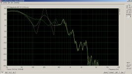
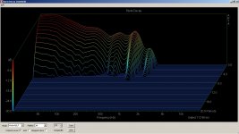
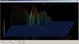
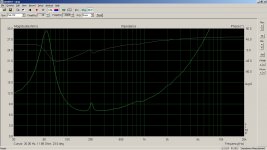
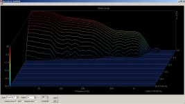
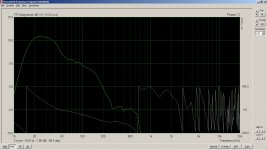
Empty box -worst case, with high peaks and deep nulls, long reverb on CSD, clear peak on impedance (only for main standing wave)
Angled bottom panel -Almost same as previous
Block of foam in the bottom -clear improvement on peaks and nulls and CSD, small bump visible on impedance
Block of foam in the middle of the box -very good, curve close to flat and CSD looking really nice. However some increased amplitude in the lowest frequencies (inside the box), indicating more pressure for the woofer to work against possibly giving less LF output. However, Fs was same as foam in bottom, and slightly lower than no foam. No peak on impedance.
Resonator in the bottom-cancelled the main standing wave pretty well (similar to foam in bottom), but the other nulls and peaks were still there unaffected. Small peak on impedance, similar to foam in bottom.
The frequency response in first picture shows Empty box, foam in bottom, and foam in center. I think it's easy to guess which is which..
The baffle is just clamped on for easy access, and I placed a measurement mic inside the cabinet behind the woofer, to see the actual back-waves acting on the rear of the cone. I also measured impedance.
Empty box -worst case, with high peaks and deep nulls, long reverb on CSD, clear peak on impedance (only for main standing wave)
Angled bottom panel -Almost same as previous
Block of foam in the bottom -clear improvement on peaks and nulls and CSD, small bump visible on impedance
Block of foam in the middle of the box -very good, curve close to flat and CSD looking really nice. However some increased amplitude in the lowest frequencies (inside the box), indicating more pressure for the woofer to work against possibly giving less LF output. However, Fs was same as foam in bottom, and slightly lower than no foam. No peak on impedance.
Resonator in the bottom-cancelled the main standing wave pretty well (similar to foam in bottom), but the other nulls and peaks were still there unaffected. Small peak on impedance, similar to foam in bottom.
The frequency response in first picture shows Empty box, foam in bottom, and foam in center. I think it's easy to guess which is which..
Attachments
-
 freq in box foam in middle.jpg194 KB · Views: 315
 -
 decay foam in bottom.jpg281.6 KB · Views: 309
 -
 decay foam in middle.jpg266.7 KB · Views: 297
 -
 decay start.jpg290.5 KB · Views: 294
 -
 imp foam in bottom.jpg190.2 KB · Views: 290
 -
 imp foam in center.jpg192.2 KB · Views: 117
 -
 imp start.jpg193.3 KB · Views: 128
Last edited:
I did some more testing today, moving around the foam block a little, and adding some poly wadding. Partly tuning by ear, and measuring after the fact.
Foam block is placed at an angle in central position, and a little bit of poly wadding on top of that.
I will add bracing for rigidity and add felt to the walls for damping higher frequencies, but I think I have made the best I can of the situation when it comes to standing waves, or are there more suggestions?
Attachments
I am not sure what to make from your measurement plots because I don't know how your measured those. Are these nearfield measurements taken close to the woofer?
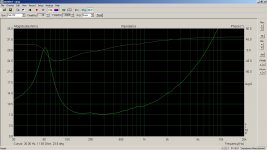
Electrical impedance would be interesting, too. If you zoom in to the frequency range(s) where the resonances happen you can often see a wiggle in the impedance curve. If the wiggle goes away after "treatment" with the absorber, you killed the resonance.
Did you look further into the chamber idea?
Electrical impedance would be interesting, too. If you zoom in to the frequency range(s) where the resonances happen you can often see a wiggle in the impedance curve. If the wiggle goes away after "treatment" with the absorber, you killed the resonance.
Did you look further into the chamber idea?
Ok, sorry if I was not clear enough.
All the FR and waterfall plots measurements in post 34 & 35 were done with the mic inside the cabinet behind the woofer, to see what's happening inside the box. You can see impedance plots in post 34 too. I measured with different stuffing, and also tried the helmholz resonator to kill the 200Hz standing wave (discussed earlier), and this time it worked fairly well, but not better than a (big) foam block in the bottom of the box. The foam block damped the 200Hz the same, but as a bonus also the multiples, which the resonator did not effect.
If you compare FR&waterfall to the impedance traces, you can see that impedance plot does not tell the whole story. Mic inside the box gives more details on what's going on, and there are no external sounds and reflections, so measurement is pretty accurate and gating is not really needed.
As a side note, this is a sealed 35L tower with a Peeless HDS P830869 8".
Ok, sorry if I was not clear enough.
All the FR and waterfall plots measurements in post 34 & 35 were done with the mic inside the cabinet behind the woofer, to see what's happening inside the box. You can see impedance plots in post 34 too. I measured with different stuffing, and also tried the helmholz resonator to kill the 200Hz standing wave (discussed earlier), and this time it worked fairly well, but not better than a (big) foam block in the bottom of the box. The foam block damped the 200Hz the same, but as a bonus also the multiples, which the resonator did not effect.
Since the boam block will act as a broad-band absorber, it will "suck out" the energy not only at the resonance frequency, but everywhere. This will reduce the overall bass SPL. The advantage of the chamber absorber is that it operates at the resonance only and does not affect the bass SPL elsewhere.
In my case I'm not worried about maximum SPL that much, quality over quantity so to say, but I get your point.
I have had the same 'feeling' about damping the box on other projects, but now I actually tried an engineering approach 🙂 I have not seen that much measurements etc on the subject, mostly blips on impedance curves, so I wanted to investigate further.
I have had the same 'feeling' about damping the box on other projects, but now I actually tried an engineering approach 🙂 I have not seen that much measurements etc on the subject, mostly blips on impedance curves, so I wanted to investigate further.
- Home
- Loudspeakers
- Multi-Way
- Extra tuned box to cancel standing waves in speaker box