Ok, so this is about standing waves (top to bottom) in tower speakers, a common problem, and can easily be seen as a bump on the impedance curve if the woofer is mounted close to the end.
I have tried killing this with internal damping/stuffing, and it works ok, but I have seen people building towers with a small resonator (separate box and port in to the main enclosure) in the bottom to cancel these standing waves, and would be interested in trying this. I'm modifying some towers that actually has a box for sand filling in the bottom and woofer at the top, so they would be a perfect candidate to try this.
Hobby Hifi (Germany) apparently had an article about it, but I have not been able to find any info on the web.
I would like to see how it's calculated and practical examples with measurements, how to fine tune etc would be even better. Should be something out there..?
Hope somebody can share links? Or experiences?
Hi,
I have no experience to share but the principle is well known and used in acoustic: this is an helmotz resonator ( aka bass trap).
There is some online calculator to help you define parameters for acoustic ones and i don't see why they would be different in your case.
That said having the volume and tuning defined is only a part of the story, the other one is to locate it ( them) in the right place for it to be effective.
Take a look at the 'acoustic' subforum there is post with links to free online calculators.
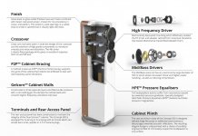
You are referring to Helmholtz Pressure Equalisers (HPE) as used in the Q Acoustics Concept 500 floorstanders.
Q Acoustics Concept 500 loudspeaker | Stereophile.com
Engineering Acoustics/Noise control with self-tuning Helmholtz resonators - Wikibooks, open books for an open world
Q Acoustics Concept 500 loudspeaker | Stereophile.com
The basic principles are referred to here:"Tuned tubes inside the cabinet quell internal resonances (standing waves) that develop in the longest dimensions of a speaker enclosure.
Q calls this Helmholtz Pressure Equalization (HPE)."
Engineering Acoustics/Noise control with self-tuning Helmholtz resonators - Wikibooks, open books for an open world
I can't see much from the picture, but here is a link with a good picture of a kit:
Merlin Lautsprecher Gehäuse Bausatz Hobby Hifi Bernd Ti

Merlin Lautsprecher Gehäuse Bausatz Hobby Hifi Bernd Ti
There's a bit of promotional blurb and video for this on the NS-5000.
NS-5000 - Speakers - Yamaha - Australia
NS-5000 - Speakers - Yamaha - Australia
Hi Rallyfinnen,
Krivium is right, it´s an internal helmholtz resonator, and it works well, not only in CB or BR, but also in TML, and I´ve even seen BLH designs incorporating the IHR.
I can make a copy of the HOBBY HIFI articles and calculations, but only in two weeks when I´m back home. Pass me a PM if you´re interested, I´m not sure if copyright allows me to post copies here?
All the best
Mattes
Hi,
Here is a link to a calculator incase you haven't find :
Helmholtz Calculator
And another one:
HiFi Loudspeaker Design
Rallyfinnen, do you have a project with data to boot on? Like the dimension of the internal loudspeaker? With the second link you can have an idea of volume it'll need and define more or less the behavior.
Last edited:
Thank you for the replies!
The original article would be too hard for me to understand, my knowledge in German is limited. Easy on websites though, with google translate 🙂
At the moment I'm busy figuring out what tweeter I should/could use from what I have 'in stock'. Just putting something together from leftovers.
The original article would be too hard for me to understand, my knowledge in German is limited. Easy on websites though, with google translate 🙂
At the moment I'm busy figuring out what tweeter I should/could use from what I have 'in stock'. Just putting something together from leftovers.
Ok.
Just in case it is easy to simulate, i've done some in the last minutes... 😉
One thing, how much volume are you willing to sacrifice from the overall loudspeaker one?
To give an idea, i've simulated a 0.8m x 0.35m x 0,25m and it needs an 1,75liter helmotz resonator to absorb the 213hz resonance ( with an effective bandwidth of 16hz, high Q) from the heigth with a simple 4cm diam hole in a 1,8cm wood panel.
All in all it'll need a bit of iteration to find the optimal volume with respect to the overall one of the loudspeaker but it is doable easily i think.
I suppose you'll have to test where to place it thoug.
Aren't there several modes inside the box? How to tune the resonator? Vertical is usually the longest dimension and it's resonance fits the passband of the woofer. Obviously you must define the net volume (original-resonator) and dimensions first!
Yamaha NS-5000 has two anti-resonators inside! Yamaha NS-5000 Loudspeakers Review & Test | Hi-Fi | Review | AVHub
Yamaha NS-5000 has two anti-resonators inside! Yamaha NS-5000 Loudspeakers Review & Test | Hi-Fi | Review | AVHub
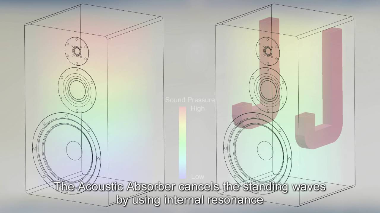
The trick with the internal Helmholtz resonator is that you tune it to the frequency of the standing wave. Then you stuff the resonator box with a lot of damping material to absorb the sound energy entering the resonator box. This sucks the energy out of the standing wave.
Hi Juhazi,
Here is how i see things: there is obviously multiple modes within an enclosure ( like a room). We have longitudinal, axial, tangential. Overall and if my memory serve this is 16 to treat.
But as stated initially the one which may be more difficult to treat by absorbtion is the axial as this is the one which will be the lower in freq.
Others should be easily be damped by absorbent material which will be used nevertheless, so i would focus on the axial one.
As you stated we will have to know net volume of loudspeaker ( overall volume) and the minimum one Rallyfinninen need for the drivers.
From then it is easy to define a maximum volume allowed for the resonator and determine the axial mode's freq.
Then you'll define tuning and bandpass of the resonator. Then tweak to find best location of input port.
It may not need to be a simple Helmotz reso, it could be a multilayer/ multiport one which open possibility to dampen multiple frequency, but it'll loose efficiency and be lower Q so it may not be optimal but treat other modes too.
If it was me i would stuck to one high Q for the axial for best performance.
I suspect this is the reason there is two in the Yamaha, to increase effectiveness, but i may be wrong.
To tune it this is determined by the diameter and depth/ height of the port.
Nothing more complicated than that from my view but here again i could be corrected.
Well said, krivium! Looks like Yammys ports are not identical but pretty close. One challenge is that the port mouth must have significant area to suck most of resonant pressure in.
I don't believe that this is actually a big problem. Much easier solution is to use heavy stuffing on the floor of the box and loose fibres up to top. A two-way speaker is much more challenging because practically all box modes happen in passband of the woofer (one big resason to avoid them in diy).
ps. some room mode sims can be used to study box modes too!
Last edited:
Try positioning the resonator hole to the pressure node of a standing wave, should be optimal place I guess since high pressure likes to go towards lower pressure.
Lowest frequency axial mode pressure nodes are at the boundaries, top and bottom in this case.
In fact, all modes have pressure nodes at the boundaries 😉 The yamaha speaker resonators seem to be at the corners, targetting all axial (did I get the right term here? between opposing walls) modes.
There seem to be holes at the other end of those resonators as well, in the middle of the enclosure. Anyone with have an idea how those work?🙂
Last edited:
Thank you for the short an simple explanation mbrennwa!
Are the Yamaha resonators open in both ends? One end in the high pressure zone, and the other in the low pressure zone? Looks like they bent them to get the other end in the middle of the box?
When it comes to my box, it's a QLN 122. Abt 30L in the main enclosure, and a small enclosure at the bottom (still filled with sand) with unknown volume, but guesstimated 1-2L. Outside dimensions: 800 x 210 x 256 mm
Drivers I'm planning to use are Vifa P17WJ and Monacor DT300. From simulation they seem to be easy to integrate with passive XO. The standard D19TD tweeter was not a good match.
Making the bottom enclosure a resonator will take some work, since the only way to access it and make a port into the main enclosure is drilling a large hole from the bottom straight through both walls of the bottom enclosure, use the upper hole (+pipe) as port, and plug the bottom hole again. I wonder if it's worth the effort compared to just stuffing the box to absorb the axial standing wave.
Last edited:
Are the Yamaha resonators open in both ends? One end in the high pressure zone, and the other in the low pressure zone? Looks like they bent them to get the other end in the middle of the box?
I don't know much about the Yamaha, but the image posted above shows that they did not use a Helmholtz resonator for sure. It looks like they put in some tubes, which seem to work as pipe resonators, tuned to the desired frequency. There was an article about this approach in a recent issue of the Hobby Hifi magazine.
... I wonder if it's worth the effort compared to just stuffing the box to absorb the axial standing wave.
Build a prototype and try it out, if you can. Stuffing might be just enough for the mid leakage not to be a problem, it is a bit hard to predict the mid leakage from the port since no simulation software available 🙂
I found out with my prototype, based on some initial hornresp MLTL simulations, that woofer at the middle height (prevents the lowest standing wave forming) and port at 1/3-1/5 of height to avoid other pressure nodes pretty much eliminated leakage from the port within the pass band and above (3-way speaker).
I'm not sure if I could identify the port leakage among all other possible flaws in my DIY effort 😀 At least it is possible to get better results by not ignoring the issue, and quaranteed results if makes a prototype and then tunes the performance. Always a compromise, it is a bit hard to get woofer in the middle given other speaker design goals.
Last edited:
Yamaha NS-5000 Loudspeakers - West Coast Hi Fi
Now I found more info of NS-5000
"The cuboid enclosure unifies internal standing waves at a specified frequency, which are cancelled by a newly developed resonance tube (patent pending). This technology eliminates the previous need for the large amount of sound-absorbing material inside the enclosure. The result is the virtual elimination of standing waves with amazing efficiency and pin-point accuracy."
- Home
- Loudspeakers
- Multi-Way
- Extra tuned box to cancel standing waves in speaker box