Psst...
What about 3-4" dome, but coaxial...
Better sensitivity, dispersion, with 25-33mm HF unit, more extended response than a 3" dome alone, as well as smooth directivity in all directions, not just horizontal.
Add a few PTT6/8/10X ...
What about 3-4" dome, but coaxial...
Better sensitivity, dispersion, with 25-33mm HF unit, more extended response than a 3" dome alone, as well as smooth directivity in all directions, not just horizontal.
Add a few PTT6/8/10X ...
Last edited:

I’m having trouble visualizing “coaxial domes.” Wouldn’t the mid then be a ring radiator, a la Andrew Jones’s “IRIS” coax for Pioneer?
That's a dome with a WG inside a torus, right?

This looks like a standard coax driver with a centrally mounted VC for the MF, no outer surround.
That would be tough to market-
"look darling- the speakers are looking at us!"
It would take a heck of an engineering feat to squeeze an convex HF unit within a convex MF unit... but was high neodymium-content magnets even available when ATC made the SM75-150S nearly 50 year ago? If not, it's no had to hang 20lbs (9kg) of motor behind a tiny 3" dome.
Today we can talk about neo and iron nitride...
Last edited:
How would the PTT6.5X04-NAA-08 perform in a 17 liters (0.6ft³) sealed enclosure? I don't have time for simulations or even building new enclosures at the moment, but I'm really itching to buy some Purifis and temporarily install them in some old boxes.
I swapped out some 8" drivers in an enclosure for the original PTT6.5X04 using spacer rings and they sound just great with no calculations or custom building. So I'd say go for it and leave the custom build till later when you have time.
Check: https://ptt.purifi-audio.com/shop/p...,5410,5411,5412,5413,5414,5415,5416,5417,7593
At the bottom it gives values for sealed and bas reflex etc
At the bottom it gives values for sealed and bas reflex etc
How would the PTT6.5X04-NAA-08 perform in a 17 liters (0.6ft³) sealed enclosure? I don't have time for simulations or even building new enclosures at the moment, but I'm really itching to buy some Purifis and temporarily install them in some old boxes.
I also lack time so here is a sim simply opening CAD and setting box to closed with 17 liters. Looks like you get F3 at 78Hz F6 at 50 Hz Qtc 0.48. My guess is with room gain (and if available a bit of bass EQ +2dB below 50 Hz) this would be quite enjoyable for "really itching to buy some Purifis and temporarily install them in some old boxes."
That's a dome with a WG inside a torus, right?
View attachment 1418216
This looks like a standard coax driver with a centrally mounted VC for the MF, no outer surround.
IRIS is the picture your words brought to my mind. I’ve also played with those - they’re fun little drivers!
You could also use examples from, e.g. Cabasse or Thiel that have suspended rigid ring radiators with concentric tweeters. That’s my point - unless the “midrange dome” has a hole in it I don’t see it. Though I guess what you’re saying is put a tweeter on the “coherer” (phase plug) of the midrange?
Yes, a hole in the midrange dome.
A small dome within another dome. The profiles would need to be different, and optimized for the frequencies that they cover.
2 motors or one motor, I don't know..
A small dome within another dome. The profiles would need to be different, and optimized for the frequencies that they cover.
2 motors or one motor, I don't know..
Hi,
conduct a fast thought experiment to come up that these things are never going to be ideal, as long as they are physical objects with static proportions.
-Sound wavelength changes greatly over the audible bandwidth.
-Physical objects affect acoustic sound per their size and shape relation to wavelength.
-thus covering whole bandwidth from single point in space would need a physical construct that is both big and small at the same time to be "ideal" for whole bandwidth, which is physically impossible.
=> split the bandwidth to two or more transducer covering different bandwidth are different size and shape to be effective and "ideal" over some smaller bandwidth, concentric or not.
Now, two physical objects cannot occupy same physical location at the same time, so they would have to mold together somehow, big and small, like a concentric driver. But, both transducers are immediate acoustic environment for the other, optimized either for their own bandwidth or for the other, but not both at the same time or you could use just one transducer with reduced bandwidth.
That said all we can do is whine about it because it's physics it doesn't align to our wants and wishes, but we must adapt to physics. Some solutions are working better than others, better implemented compromises with various trade-offs are available, so just pick one suitable.
It's fun to wonder about this stuff so, keep on 🙂
TL; DR
Are you saying it is impossible?
2 drivers sharing 1 magnet-

Woofers without a surround-
Are you saying it is impossible?
2 drivers sharing 1 magnet-
Woofers without a surround-
Last edited:
A ~ mini inverted Altec biflex (single motor).Yes, a hole in the midrange dome.
A small dome within another dome. The profiles would need to be different, and optimized for the frequencies that they cover.
2 motors or one motor, I don't know..

Quick question. For the PTT6.5M (paper). With regards to high SPL and THD under ~150hz, would a 2nd order high pass circa 250hz be too low?
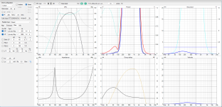
Here's 12L sealed near field, then far field 1m merged to nearfield with baffle step correction, 1/12 smthHow would the PTT6.5X04-NAA-08 perform in a 17 liters (0.6ft³) sealed enclosure? I don't have time for simulations or even building new enclosures at the moment, but I'm really itching to buy some Purifis and temporarily install them in some old boxes.
You could do a check in vituixcad to see how that reduces the excursion.Quick question. For the PTT6.5M (paper). With regards to high SPL and THD under ~150hz, would a 2nd order high pass circa 250hz be too low?
The thd at low frequencies is largely dependent on excursion. So if you have thd measurements they should also say how they were measured and from that you can guestimate what happens if excursion is of say 1mm .
Assume measurement at 2,83 Vrms and full bandwidth withbdriver in closed box or infinite baffle, you can sim that. It gives you an indication of the excursion in that test.
As it is a midrange it has a short voicecoil, thus limited excursion.
Sort of combining these gives an good indication.
Assume measurement at 2,83 Vrms and full bandwidth withbdriver in closed box or infinite baffle, you can sim that. It gives you an indication of the excursion in that test.
As it is a midrange it has a short voicecoil, thus limited excursion.
Sort of combining these gives an good indication.
In the meantime, I have been able to measure my PTT6.5X04-NAA-08s.Here's 12L sealed near field, then far field 1m merged to nearfield with baffle step correction, 1/12 smth
Last edited:
- Home
- Loudspeakers
- Multi-Way
- Exploring Purifi Woofer Speaker Builds