One's done, and I was about to do the other when I was distracted by finding a really nice piece of cherrywood, perfect for the case of the USB DAC project I've been trying to finish for a while, so I started on that instead! 😉
it's change from 800-500mVMikeB said:
500 mv ? Uaaah ! That's idle bias of ~2.4amperes ! Yes, the 2A fuse will blow... No wonder that it runs hot. Changing the trimpot does not change that value ?
Mike
Voltage accross r15/17 (150 ohm) is 215mVMikeB said:
What is the voltage across r15/17 now ?
Are you sure that r10 is 68ohms ?
You should also verify the values of r23/24 (2k/500ohms)
Mike
R10 is correct 68 ohm
R23/24 is correct to 2K/500 ohms
MikeB said:
Btw, are you familiar with ohm's law ?
Mike
yes V=I * R (I in Ampere and R in Ohm ? )
0.22 Ohm 5W is measure at 0.8 ohm
4.7 Ohm is measure at 5.4 ohm (carbon resistor)
1.2 Ohm is measure at 1.8 ohm (carbon resistor)
10 Ohm is 10.6 Ohm (carbon resistor)
I don't know is correct or not because is very cheap Digital multimeter.
other R value are correct.. I check it 3 times
Transistor is
Q1,Q2 = BC547B (pin reversed )
Q7,Q8 = BC546B
Q3,Q9 =2N5551
Q4,Q5,Q12 = 2N5401
BD139
MJE15030
MJE15031
How to lower bias outstage, maybe because Fake toshiba 2SA1302A and toshiba 2SC 3281A ?
I don't think that the fake output transistors can cause that...
Can you give a reading across r26 ? It should be ~1.2v.
Ohms law is I = V/R or V = I*R or R = V/I.
Means, 1.5ma through a 680ohms give 1.02v.
Or: 500mv across a 0.22ohm give 2.27ampere.
Mike
Can you give a reading across r26 ? It should be ~1.2v.
Ohms law is I = V/R or V = I*R or R = V/I.
Means, 1.5ma through a 680ohms give 1.02v.
Or: 500mv across a 0.22ohm give 2.27ampere.
Mike
MikeB said:I don't think that the fake output transistors can cause that...
Can you give a reading across r26 ? It should be ~1.2v.
Ohms law is I = V/R or V = I*R or R = V/I.
Means, 1.5ma through a 680ohms give 1.02v.
Or: 500mv across a 0.22ohm give 2.27ampere.
Mike
voltage accross R26 is 3.24v
hmm, that's way too much, it seems like something around the trimpot or bd139 is wrong...
Mike
Mike
MikeB said:hmm, that's way too much, it seems like something around the trimpot or bd139 is wrong...
Mike
R23 2k ohm measure at 1954 ohm
R24 500 ohm measure at 495 ohm
R22 trimpot 1k , I Use 500 Ohm now measure at 470 ohm
R8/R9 22 Ohm Measure at 22.8/22.9 Ohm
R26 is 33 Ohm Measure At 33.5 ohm
I change BD 139 with New One (BD139 with Hfe 152)
voltage accross R26 is still 3.24v
Where is the problem now ?

Hi dytln_02,
Is it possible to have someone else look at your work on the board? A second pair of eyes.
Meantime, leave the room. Do not say anything to this person except that you need to have the board checked for errors. Do not talk to that person any further until they are done.
There are some pictures of completed and nearly completed boards earlier in the thread, as well as on Mike's web page. Compare them.
-Chris
check all transistor and is ok
finaly I change Toshiba 2SC3281/2SA1302 with 2SC5200/2SA1943
330 pf change to 220pf
voltage across
- R26 = 1.2v
- R 0.15 Ohm = 3mV
- R 680 ohm =1.67v
- R 150 ohm = 1v
- R 68 ohm = 0.9v
dc offset is 4v
Now I'm Crazy
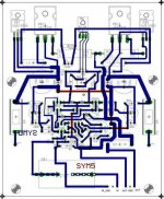
I want to make new board
can you help me cek my layout, i modified because i can not put R 0.15 ohm and 4.7uF
finaly I change Toshiba 2SC3281/2SA1302 with 2SC5200/2SA1943
330 pf change to 220pf
voltage across
- R26 = 1.2v
- R 0.15 Ohm = 3mV
- R 680 ohm =1.67v
- R 150 ohm = 1v
- R 68 ohm = 0.9v
dc offset is 4v
Now I'm Crazy
I want to make new board
can you help me cek my layout, i modified because i can not put R 0.15 ohm and 4.7uF
An externally hosted image should be here but it was not working when we last tested it.
Attachments
Hi dytln_02, looks like the amp was oscillating with the other output devices and because of that gave wild readings. I don't know what you had changed to get the other values ?
I guess it's best to restart all over and doublecheck everything.
In your pcb your new traces are way to thin, make them as they were.
The voltage across the 680ohm is now too high, this causes the others to increase. At least r26 is now normal.
Mike
I guess it's best to restart all over and doublecheck everything.
In your pcb your new traces are way to thin, make them as they were.
The voltage across the 680ohm is now too high, this causes the others to increase. At least r26 is now normal.
Mike
Hi dytln_02,
If you sure that you did everything right then probably you got fakes (palsuuuu!!) outputs transistors. It is our problem men! It is hard to find original discrete in here.
I see original ON (was Motorola Mexico) MJ15003/15004 that could make better result that toshiba's or sanken (most of toshiba and sanken in here are fakes). They are arround Rp. 25.000,- per pc or Rp. 50.000,- per set. Hor much did you buy your Toshiba's?
The fakes parts only wasting your time.
How high your voltage supply level?
In@kartino, Toshiba 2SC3821/2SA1302 is only $1.5 (IDR 14.000)
Per set . fake yes i buy cheaper version...
Another version is $3.5 (IDR 3.5000)
Using 2SC5200/2SA1943 is working.... is only $2 (IDR 18.000).
One board is working ok dc offset 35mV.
@mikeB
Change With 2SC5200/SA1943 first board is now working.
yesterday it's not working because I Change BC549 with BC547 and it's reverse. (like MPSA 18). Fix it And it's Working. Sound good
In second board i have problem dc offset is ~40mV. I hear loud distortion.. (it's the same component) and Maybe gain is bigger because i hear louder sound than first board
Voltage Across
R 0.15 Ohm = 15mv
R 33 Ohm =1.19v
R 680 = ~0.95v
r 8/9 = 1.7mv/7.6mv
R 22 Ohm = 0.18v
R 68 Ohm= 0.32v
R 150 Ohm = 0.35v
R 220 Ohm = 0.62v
R 47K = 1.22v
R 1.2Ohm = 1mv
I only change
- 330pf with 220pf
-10pf with 3pf
- MPSA18 with 547B.
May be it's oscillating, it hotter than first board.., but not too hot
How to fix it ?
@mikeB
Thanks you very much.....
Now All is working... Sound Good...., but dc offset is 35mV in first board and in second board is 38.5mV. in second board i have macth hfe but it's not work.
Is this save for speaker ?
What differences using high hfe Transistor like MPSA18 with Low hfe BC547B (it's only ~350) ?
Hi dytln_02, <40mv is okay for the speakers, but if you did match hfe for inputtransistors the dc-offset is way too high. hfe of 350 is not really low and can't cause dc-offset unless you omit the inputcap or the feedback cap, or you don't have 22k for both the r14 & r29.
Have you changed a resistor here ? Something is still wrong...
Did you also match q4/12 ? and q3/9 ?
Please check if r14 & r29 are really 22k, if you use 10k on one side you will get ~40mv offset with hfe of 350.
Can you measure voltages at the bases of the inputtransistors to ground ? (Disconnect speakers when measuring that)
With hfe of 350 you should have ~94mv on both sides.
Mike
Yes Q4/12 and Q3/9 is match i can remember hfe value but i have matching it..MikeB said:Hi dytln_02, <40mv is okay for the speakers, but if you did match hfe for inputtransistors the dc-offset is way too high. hfe of 350 is not really low and can't cause dc-offset unless you omit the inputcap or the feedback cap, or you don't have 22k for both the r14 & r29.
Have you changed a resistor here ? Something is still wrong...
Did you also match q4/12 ? and q3/9 ?
Mike
R14 / R29 = 21.9k Ohm
Do you mean voltage at here look picture below ( betwen MPSA18 there is 2x 47 Ohm Resistor
I use + 31.2v 0 -31.2 5A PSU
An externally hosted image should be here but it was not working when we last tested it.
Soryy : It's Not MPSA18 But It BC 547B
Hmm, 😕 with these readings and matched transistors and fitting 22k's DC-offset should be 3.7mv... (The value to be expected from symasym) Maybe you measured the DC-offset wrong ? Have you cleaned the PCB after soldering ? Maybe you got very bad 470uf elyts ?
Mike
Mike
MikeB said:Hmm, 😕 with these readings and matched transistors and fitting 22k's DC-offset should be 3.7mv... (The value to be expected from symasym) Maybe you measured the DC-offset wrong ? Have you cleaned the PCB after soldering ? Maybe you got very bad 470uf elyts ?
Mike
I measure from "X" to ground See Picture Below
An externally hosted image should be here but it was not working when we last tested it.
I clean Up PCB after Read your answer. Change All Transistor BC547B (hfe 302) , 2N5551 (hfe 200), 2N5401 (hfe 198 I ' don't Remember but it's match pair ).
Caps 470uF/50v Measure at 430uF With Digital Caps Meter
DC offset it's Still 35mV........Maybe it's Fake 2SC5200/2SA1943

How About change 2SC5200/2SA1943 with MJ15003/15004 ?
What value must Change with MJ15003/15004 ?
yesterday I Change 3pf Caps with 2pF caps I hear more treble and mids more Open.. (Sound Like Gainclone LM1875 at treble and mids but with more bass)
it's Ok to change 3pf caps with 2pf
Hi dytln_02, i meant measuring the dc-offset, it should be 1/10 of your reading. The values at the input transistors show that he amp sees only 3.7mv dc-offset. Can you measure the difference between power-gnd and signal gnd ? (Voltage across r2, the 10ohm)
Maybe you have a grounding problem in your setup.
I can't recommend the mj15003/4 for symasym, they are too slow and have low gain. I don't think that your outputdevices cause that.
BTW, it's not necessary to match the 2n5401 against the 2n5551, it's enough to match the 3 pairs.
You can play with c14, just make it not too big (oscillation), making it too small can give bright sound because of overshooting and again oscillation. (do not go above 10pf) High quality cap is here very important, any distortion from this cap will be in the output.
Mike
@mikeb
PSU +31v 0 - 31v 5A
See Picture I have Measure
Digital multimeter only mV there is no uV
inductor solder at 10 ohm Resistor
I use Potentio 100K at input
PSU +31v 0 - 31v 5A
See Picture I have Measure
Digital multimeter only mV there is no uV
inductor solder at 10 ohm Resistor
I use Potentio 100K at input
An externally hosted image should be here but it was not working when we last tested it.
- Home
- Amplifiers
- Solid State
- Explendid amplifier designed by Michael Bittner, our MikeB