dytln_02, you shouldn't use a pot that big (100k), this will degrade quality, 22k is a better value.
About your DC-offset, it's like i suspected, it's a grounding issue, you have 46mv DC-offset on the signal-gnd, causing 4.6ma to flow through the 10ohms. What is your signalsource ? Have you earthed something in your setup ? The DC-offset should reduce to a few mv if you disconnect the signalsource. If not, we have a problem...
If yes, measure the voltage between gnd of disconnected source and gnd of amp. Be aware of quite high voltages to expect, enough to shake you.
Mike
Chuck911 said:Still in slow progress. Tomorrow may be I can bring them to life.
An externally hosted image should be here but it was not working when we last tested it.
Cheers
Karel
Hi Karel, any news ?
Mike
Signal source use computer soundcard.MikeB said:About your DC-offset, it's like i suspected, it's a grounding issue, you have 46mv DC-offset on the signal-gnd, causing 4.6ma to flow through the 10ohms. What is your signalsource ? Have you earthed something in your setup ? The DC-offset should reduce to a few mv if you disconnect the signalsource. If not, we have a problem...
If yes, measure the voltage between gnd of disconnected source and gnd of amp. Be aware of quite high voltages to expect, enough to shake you.
Mike
it's measure with no input connected.
With input connected it's the same.
I try to measure disconnected GND input source with GND amps it's give wild reading from zero to 7mv
no i don't earth, because there no earth in AC wall.
Try to connected GND to floor it's the same dc offset at signal-gnd.
Can it cause by bad PSU.......?
I only use
- 2x 10.000uF/50v
- 4x diode 3A
- +25 CT -25 5A transformer (Cheap transfomer)
10.000uF caps measure At 9.000uF and 8.200uF
I try to change 10 Ohm with 68Ohm at input.
dc offset at signal - gnd is the same.
it's cause by BC547B..
I try Change BC547B with BC550 with hfe 430 and 433,
now dc offset is now is 22mV at 10ohm output
and dc offset at signal is
see picture
Can you suggest replacement for MPSA18 with high hfe.
I can not get MPSA18.
dc offset at signal - gnd is the same.
it's cause by BC547B..
I try Change BC547B with BC550 with hfe 430 and 433,
now dc offset is now is 22mV at 10ohm output
and dc offset at signal is
see picture
An externally hosted image should be here but it was not working when we last tested it.
Can you suggest replacement for MPSA18 with high hfe.
I can not get MPSA18.
dytln_02, you can keep the bc547 or bc550, they are ok. It's only the difference in gain between the 2 that counts.
Sorry, i didn't read correct, i thought you measure 46mv across r2. Can you confim that you read 0v across r2 ? I guess reading 46mv at the input of the amp in front of the 4.7uf was a mistake ?
Keep r2 with 10ohms, a higher value increases the risk of dc-offset because of grounding problems.
How do you match your transistors ?
Your readings can only be caused by 3 problems:
1, heavily mismatched devices in the input (hfe of 420 to 210 for example)
2, unmatched resistors (22k,r14/29)
3, shorted feedback cap (470uf/100nf,c19/20), or leaking c14 (check for solder bridges, is the 100nf ok ?)
Can you please tell the sign of the DC-offset ? (positive or negative, read with the black probe connected to ground, red to output)
Mike
EDIT: are your 470uf of the same quality like the exploding ones ? You could make 2 tests: solder it out (keep the 100nF !!!) and check DC-offset, short it and check if dc-offset changes.
If soldering it out changes DC-offset, this cap is garbage.
Without the 470uf you will have no bass.
Don't forget to check the 100nF also.
MikeB said:dytln_02, you can keep the bc547 or bc550, they are ok. It's only the difference in gain between the 2 that counts.
Sorry, i didn't read correct, i thought you measure 46mv across r2. Can you confim that you read 0v across r2 ?
Yes, it's 0v Across R2
MikeB said:
I guess reading 46mv at the input of the amp in front of the 4.7uf was a mistake ?
it's - 35mv (minus)
MikeB said:
How do you match your transistors ?
using digital multimeter
MikeB said:
Your readings can only be caused by 3 problems:
1, heavily mismatched devices in the input (hfe of 420 to 210 for example)
2, unmatched resistors (22k,r14/29)
3, shorted feedback cap (470uf/100nf,c19/20), or leaking c14 (check for solder bridges, is the 100nf ok ?)
Can you please tell the sign of the DC-offset ? (positive or negative, read with the black probe connected to ground, red to output)
Mike
EDIT: are your 470uf of the same quality like the exploding ones ? You could make 2 tests: solder it out (keep the 100nF !!!) and check DC-offset, short it and check if dc-offset changes.
If soldering it out changes DC-offset, this cap is garbage.
Without the 470uf you will have no bass.
Don't forget to check the 100nF also.
hfe 430 /433 (BC550)
R14/29 using digital multimeter value is 21.9K/21.9k
remove 470uF
- R29 to GND -40mV (minus)
- R14 to GND -35mV (minus)
- output dc offset +25mV
Remove 470uF and 100nF
- R29 to GND 0mV (minus)
- R14 to GND -0mV (minus)
- output dc offset +224mV
Mike I Have 2 Board and give the same problem
Hi Mike,
thanks for asking. I am very busy with my semestral work on university. But I´ve received my heatsinks last week. May be I can have my transformer next week. During my projects on school I´m still working on universal power supply with better passive filtration and integrated DC-protection with supply shutdown. I will come with all results and measurements.
Regards
Karel
thanks for asking. I am very busy with my semestral work on university. But I´ve received my heatsinks last week. May be I can have my transformer next week. During my projects on school I´m still working on universal power supply with better passive filtration and integrated DC-protection with supply shutdown. I will come with all results and measurements.
An externally hosted image should be here but it was not working when we last tested it.
An externally hosted image should be here but it was not working when we last tested it.
Regards
Karel
dytln_02, what was the DC-offset before removing the 470uf ? +22mv ? I guess DC-offset didn't change and the cap is ok.
I did tell you "Keep the 100nF !!!" with 3 "!", with removing the 100nf you made the amp oscillate...
Have you verified that the r16/19 (emitter resistor to input resistors) are both exact 47ohms ? (For a quick check you can short them) I am running out of ideas.
A positive DC-offset indicates that the 470uf is not guilty.
22mv dc-offset do not hurt, maybe you just keep things, its just that with these matchings it should be far below 10mv.
Assuming the 47ohms are identical, your readings show hfe of q1 = 419 and q2 = 236 (for +22mv DC-offset), maybe your dmm is playing games with you ?
Also mje15030 shows hfe of 104 and mje15031 of 499 ? 😕
Karel, is this is some ignition testing for motorbike engine ?
Mike
EDIT:
Do both boards show the same sign for dc-offset ? (positive)
Does swapping q1 and q2 change the sign of the dc-offset ?
Ignition is one part of this project. My friend is working on it. But my objective is to develop the system for injection of fuel with integration of ingnition of my friend. In our programme for near future is research and development of hydrogen injectoin into spark ignition engines. This gasoline injection is only mind-training because we are only electrotechnics.
A hydrogen driven engine ? Ouch, that must be built quite robust ? Hydrogen explosions are the nearly most brute chemical explosion. (Only topped by H2+F, reaching nuclear dimensions...)
Or is the hydrogen injected while igniting ?
Mike
Or is the hydrogen injected while igniting ?
Mike
You arent right Mike. Hydrogen is with his method of ignition near gasoline. Hydrogen is only even more calorific so that you must charge less quantity. There are another problems like melting of metal parts exposed to hot fumes or self-ignition of hydrogen mixture during intake caused by hot parts of the valve. But dont care. I´ve got solutions on my mind to solve major part of problems that we have. But I dont want to solve it on audio forums and annoying other members.
MikeB said:Assuming the 47ohms are identical, your readings show hfe of q1 = 419 and q2 = 236 (for +22mv DC-offset), maybe your dmm is playing games with you ?
Also mje15030 shows hfe of 104 and mje15031 of 499 ? 😕
thanks mikeB
I have 2 DMM try to check transistor it's give 320hfe and 310hfe
but DMM is very cheap is only $3 (made in chinese 😀 )
I measure and i see drop hfe about 5 hfe
May be because bad transistor, It's from chinese.
and it's very cheap May be hfe will drop with bigger load....
I Will try on third board. because my first board is not good (it's only test board).
Can you suggest replacement for MPSA18 with high hfe.
I will try, may be hfe not drop too much.
dytln_02: Try to test your semis by simple testing circuit. This hfe testers in cheap Chinese DMMs are unusable. They´re testing semis with very low current (far away from your application) and/or their accuracy is terrible.
dytln_02, the bc547b is definitely not a bad choice, Pavel (PMA) uses them in his symasym, and the bc550c is used by most symasym builders as it is a "standard" substitution to the mpsa18. Another possibility is the 2sc2240, but is an expensive one. Using higher gain tranistors will only reduce your problem, not solve it. Matching devices here is mandatory.
If you simply swap q1/2 in one board and the DC-offset changes it sign, the matching with your dmm does not work and we found the problem.
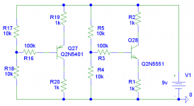
You can use a very simple circuit for matching, it consist of 5 resistors and a socket, and is suitable for npn and pnp small signal transistors. (Match/measure the resistors before using)
You measure the voltage across the 1k to the emitter (V1) and across the 100k (V2). The hfe of the transistor is then: hfe = (V1/V2)*100.
It's not perfect, but works. You can also measure idss of jfets with this circuit. As socket i used a dip-8 socket typically used for opamps.
Use a fresh 9v-battery, or the measurings change during the matching process...
If your dmm uses way too low current for measuring, the results are useless as Karel said, you could also use a random generator...
Mike
If you simply swap q1/2 in one board and the DC-offset changes it sign, the matching with your dmm does not work and we found the problem.
You can use a very simple circuit for matching, it consist of 5 resistors and a socket, and is suitable for npn and pnp small signal transistors. (Match/measure the resistors before using)
You measure the voltage across the 1k to the emitter (V1) and across the 100k (V2). The hfe of the transistor is then: hfe = (V1/V2)*100.
It's not perfect, but works. You can also measure idss of jfets with this circuit. As socket i used a dip-8 socket typically used for opamps.
Use a fresh 9v-battery, or the measurings change during the matching process...
If your dmm uses way too low current for measuring, the results are useless as Karel said, you could also use a random generator...
Mike
Attachments
Michael,
I guess you know why I spoke about 46mV DC /shown by dytln/ measured behind 4.7uF capacitor (i.e. at the input). This indicates interference into DMM leads and to incorrect mV DC measurements.
I guess you know why I spoke about 46mV DC /shown by dytln/ measured behind 4.7uF capacitor (i.e. at the input). This indicates interference into DMM leads and to incorrect mV DC measurements.
Hi Pavel, my guess was that the dmm has very high input impedance, if the 4.7uf is initially discharged, it will "bootstrap" the 46mv from the other side. If this cap is high quality and the air dry, this voltage will stay for several minutes. But it should drop while measuring, slowly charging the cap with -46mv through the dmm, what do you think ?
In the worst case the dmm has fet input...
I remember that effect from mosfets playing games with me while i tried to measure them with a dmm. (with only 1nf gatecharge)
Mike
In the worst case the dmm has fet input...
I remember that effect from mosfets playing games with me while i tried to measure them with a dmm. (with only 1nf gatecharge)
Mike
Michael,
I agree. I have mentioned HF interference as I already faced it in praxis.
Please excuse my a bit delayed replies due to "moderating". But these times of "previews" are getting shorter.
Pavel
I agree. I have mentioned HF interference as I already faced it in praxis.
Please excuse my a bit delayed replies due to "moderating". But these times of "previews" are getting shorter.
Pavel
MikeB said:dytln_02, the bc547b is definitely not a bad choice, Pavel (PMA) uses them in his symasym, and the bc550c is used by most symasym builders as it is a "standard" substitution to the mpsa18. Another possibility is the 2sc2240, but is an expensive one.
Mike
I have 2SC2240 but how to put it ? I mean Tr Pin (emmiter , collector , base)
What Caps for psu is 2x15.000uF is enough ?
Can I Use 5A +31-0-31 how many this amps will give power ?
PMA said:Michael,
I guess you know why I spoke about 46mV DC /shown by dytln/ measured behind 4.7uF capacitor (i.e. at the input). This indicates interference into DMM leads and to incorrect mV DC measurements.
Yes it's maybe, sometimes it's give wild reading
if I use 2SC5200/2SA1943, Is correct change
- 22pF with 3,3pf
- 0.22 Ohm with 0.15 ohm
- 330 with 220pF
Hi dytln_02, sorry, i did not check pinout of sc2240, it's not an option...
Your psu with 31v 5a and 2x15.000uf is good, this should give ~45watts into 8 ohm.
Have you tried to swap q1 with q2 in one board to check if the matching is the problem ? Matching is not only necessary for dc-offset, it's also important for quality. This would be the easiest way to finally find out if this is the problem.
Mike
dytln_02 said:
if I use 2SC5200/2SA1943, Is correct change
- 22pF with 3,3pf
- 0.22 Ohm with 0.15 ohm
- 330 with 220pF
Yes, though 0.22 - 0.15 exchange is not necessarily needed.
Regarding HF, not only interference into leads, but also HF oscillations superimposed on DC may lead to wild readings, as one never knows how slow DMM circuits will integrate this mess.
- Home
- Amplifiers
- Solid State
- Explendid amplifier designed by Michael Bittner, our MikeB