pinkmouse said:
Have you done what Mike suggested yet about testing with the output stage isolated?
how to test it ?
I will try again, tommorow.
I must buy fuse.
Hi Al,
I've found that matches with the hFE feature on your DMM line up pretty good with "real life". It's always good to confirm this. I have with power outputs and my Heathkit IT-18.
I am trying to find the transfer toner stuff for laser printers. I used to make positives with rub down transfers and ink. No longer have the time for that stuff.
-Chris
I just use glossy Epson bubblejet photo paper and the Lexmark laser at work. I have previously found though that different photopapers work better with other types of laser printer. Anyway, tomorrow is matching the MPSA18s and the 2N5401, and drilling. I'm still looking for an input cap that will fit the board though, I might have to go outboard for the time being.
Don't feel bad Al. They are both expensive and out of stock here. I am using 1 uF film. Tough.
A board redesign if these work out would be good. Make the spacing wider on some components.
Even the polystyrenes I ordered are back ordered. phhh.
-Chris
A board redesign if these work out would be good. Make the spacing wider on some components.
Even the polystyrenes I ordered are back ordered. phhh.
-Chris
dytln_02 said:I worry my transformer is very hot ....
I want add fuse between Transformer and Wall
What Fuse rate (value) Must be use ?
Do you use insulation / mica and washer when mounting output transistor to heatsink ?
your fuse always blow and the transformer very hot, looks like something short in your circuit.
rgds,
Gede
G33/33 said:
Do you use insulation / mica and washer when mounting output transistor to heatsink ?
Hi Gede: Some anodized heatsinks do not require insulation but most of them do. You can easily test for short between the transistor leads and the heatsink or the ground to see if there is a problem.
How do you do that hfe testing??🙄I've found that matches with the hFE feature on your DMM line up pretty good with "real life".
Hi dytln_02, G33/33 is right, it's likely that you have a short somewhere, it needs a lot of current to smoke a transformer.
Measuring the bias is easy, just measure the voltage from the left top wire of the 0.22ohms to the right top wire, you need to measure ~25mv. I have written this on my webpage. At which setting is the trimpot ? Did you use 1k or 470ohms ? What is the rating of the transfomer ?
Have you measured the supply voltages on the board ? Your readings are still too low, the 22ohms for r31/32 are ok, these don't cause problems. By accidently having 22ohms for r11 its likely that you fried q7, try to replace it. It had to dissipate 1watt, way too much for a small signal transistor. What transistor are you using for q1/2 ?
Hi Al, the 2n5551 does not need close matching, they have thermal drift anyway. I matched the mpas18 to <1%, having hfe of ~890/891, the 2n5401 to ~150/151. This needed about 5 devices. That gives ~3mv dc-offset. These 3mv are caused by the thermal drift between q3/9. Immediately after turning on i measure 0mv.
btw, nice etching !
Chris, mje15030/1 out of stock ? I could send you some micas and mjes from my collection.
Mike
G33/33 said:
Gede
Hi Gede: Sorry I did not mean to post my last post. I thought your post was by dytln_02. My apologies.
tttking said:
Hi Gede: Some anodized heatsinks do not require insulation but most of them do. You can easily test for short between the transistor leads and the heatsink or the ground to see if there is a problem.
tttking said:
Hi Gede: Sorry I did not mean to post my last post. I thought your post was by dytln_02. My apologies.
No problem Tim.
Anodized heatsink is very hard to find here, so i believe he won't use anodized HS.
rgds,
Gede
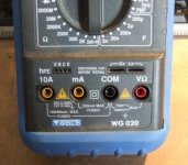
Ryssen said:How do you do that hfe testing??🙄
If you look middle left in the pic below you can see the sockets in the meter. You just set the DMM range for hFE testing, then plug in the component, (taking care about orientation), and the hFE is shown on the meter. Give it a couple of seconds to stabilse, then pull the trannie and write the value on the side. It takes about ten seconds per component once you get going.
Attachments
Yes my DMM have that hfe thing,😎 always wondered what it was for.😀 (what a dumbass I am)🙄 Is it all that is needed for matching?what about the output transistors?
Hfe
Pinkmouse
I have a meter just like yours even though the brand name and
the model number is different.
But the rest is the same, this meter is the one I use to match transistors.
BTW this meter cost me $30, cheap but effective in all the ranges and functions.
Pinkmouse
I have a meter just like yours even though the brand name and
the model number is different.
But the rest is the same, this meter is the one I use to match transistors.
BTW this meter cost me $30, cheap but effective in all the ranges and functions.
Hi Mike,
I am going to reorder soon from another vendor. Their web pages all show out of stock at this time. I have ton's of mica though. Nothing to put on it.
-Chris
Thanks for the offer, but the postage is worth more than the parts. Mine should wander along soon. Some day.Chris, mje15030/1 out of stock ? I could send you some micas and mjes from my collection.
I am going to reorder soon from another vendor. Their web pages all show out of stock at this time. I have ton's of mica though. Nothing to put on it.
-Chris
Hi Ryssen,
I use a Heathkit tester for the larger transistors. It runs them at a slightly higher current than the meter I use for signal transistors. This meter is very similar to the one Al shows, but older.
To confirm, I built a jig where I can mount as many as 4 TO-3 devices, another jig for Mosfets. I find close matches then mount them all on the heatsink. The case temperatures are now close (have a digital thermometer too). I then measure the collector currents after setting them to the "ballpark" area I want them to be. It's a pain in the butt. The proof is that when I measure the bias current sharing in a working amp, the currents are then very close between the parts.
-Chris
Do you have any schema for the jig?🙂To confirm, I built a jig where I can mount as many as 4 TO-3 devices
Hi Ryssen,
It's pretty simple. All the emitters are tied together in two groups of two with heavy wire (14 GA solid I think), connected together at the terminal. The bases are all common off a buss, a resistor (1K, matched) from the buss to each base terminal. The collector leads all have a 1 ohm (matched) resistor in series. The resistors are common to the collector terminal.
In this way, the transistors can each have their collector and base currents measured while they are close in temperature. I can calculate beta from this if I want to.
-Chris
My My Transfomer is very hot and Heatsink is very hot in 5 minutes ?? 
my transfomer is 5A +18 0 -18V,
I have change MPSA18 with BC549 Pin Reverse i got 6.3 mV
change with BC547B (hfe 325) Pin Reverse I Got 2mV DC offset
R31/32 is 47 Ohm
Q7/Q8 is BC546B and is ok
Trimpot is 500 Ohm
heatsink 0.5mm size
it's play music
If I put Fuse 2A it will blow, change with 3A is ok ( I cannot get 2.5A)
-Voltage accros R 0.22 ohm is ~ 500mV ... (adjust Trimpot is the same)
-Voltage accros R5/R6 (680 Ohm) is 0.91v
my transfomer is 5A +18 0 -18V,
I have change MPSA18 with BC549 Pin Reverse i got 6.3 mV
change with BC547B (hfe 325) Pin Reverse I Got 2mV DC offset
R31/32 is 47 Ohm
Q7/Q8 is BC546B and is ok
Trimpot is 500 Ohm
heatsink 0.5mm size
An externally hosted image should be here but it was not working when we last tested it.
it's play music
If I put Fuse 2A it will blow, change with 3A is ok ( I cannot get 2.5A)
-Voltage accros R 0.22 ohm is ~ 500mV ... (adjust Trimpot is the same)
-Voltage accros R5/R6 (680 Ohm) is 0.91v
dytln_02 said:-Voltage accros R 0.22 ohm is ~ 500mV ... (adjust Trimpot is the same)
-Voltage accros R5/R6 (680 Ohm) is 0.91v
500 mv ? Uaaah ! That's idle bias of ~2.4amperes ! Yes, the 2A fuse will blow... No wonder that it runs hot. Changing the trimpot does not change that value ? What is the voltage across r15/17 now ?
Are you sure that r10 is 68ohms ?
You should also verify the values of r23/24 (2k/500ohms)
0.91v across r5/6 is still a bit low, but ok for now.
See the good side, if your output transistor would be bad fakes they would already have popped.
You have definitely one more mistake somewhere.
Btw, are you familiar with ohm's law ?
Mike
pinkmouse said:Exactly! You should never plug anything into the wall that isn't fused on the input.
Ooops, i never did...
 Trusted on the mains fuse...
Already drilled your boards ?
Mike
- Home
- Amplifiers
- Solid State
- Explendid amplifier designed by Michael Bittner, our MikeB