Cortez,
These local caps should be as close as possible (<5cm) to the outputdevices, and have to be directly connected in "series" (their groundconnection), also as short as possible. If you manage to place the maincaps that close, you can of course skip the local ones.
Mike
These local caps should be as close as possible (<5cm) to the outputdevices, and have to be directly connected in "series" (their groundconnection), also as short as possible. If you manage to place the maincaps that close, you can of course skip the local ones.
Mike
Re[01]: Post #1093
Pavel,
I am just at this Post #1093 (just half way though thread, gosh this in one long thread *panting* and this post must feel like it was made in "stone age" lol lol )
http://www.diyaudio.com/forums/showthread.php?postid=768933#post768933
of yours of 17th November 2005 13:11:03 as I read this very very long thread. I want to say the approach you are using for the wiring is very interesting. I am not an engineer, but for many years I have thought about using a shielded cable between units where the gound of the shield is only connected at one point. This way, as I am sure was part of your intent, one avoid ground loops between units while "extending" chassis ground for the cables. It never entered my mind to use a XLR connetor to faciliate this approach.
I applied this technique for the speaker cables of my modest Sinclair amplifier in late 1970s. I used a sheilded pair cable grounding the the shield to the chassis to remove the large signal being on the 15 floor and in line of sight of a local radio transmission tower in line of sight on top of a building due south about 4 blocks of the south suite I was in. The RFI filters the government communications licencing body were not effective. I could prove the cause was speaker cable were acting as an antenna by disconnecting and listening via headphones. The shielding of the speaker cable was very effective to the RFI issue. The cables only had to run about 5 feet from the amp to speakers. Clearly the 3-4 blocks, being line of sight, south end so could see transmission antenna of local radio station and I am sure the transmission power were all strong factors to the problem. I never had a problem until I moved into this 15th floor suite. Previously I was about 1.5 miles away from this transmitter I new existed, but never really registered in my mind.
About 10+ of years back I actually used a similar approach to your noted cabling for a antenna amplifier. It was to a very well known company that did not seem to properly amplify the antenna signal before the receiver. When I open the antenna amplifier out of curiousty I discovered my horror the wiring from the coax chassis connecter near the transformer to the circuit used some cheap basic hook up wire. Two seperate loose wires, not twisted together, that passed about 1/4 inch along EF transformer lamiate and across in diangle fashion rear corner to oppsite front corner of the internal chassis. I could not believe it. My common sense, not being a EE, was this had to be replaced. I replaced these two hookup wires from the chassis coax connecter to the place where the hook up wires were connected to the circuit.
Oh my goodness I could not believe the difference. Now the antenna amplifier behaved as I expected as I used the frequency and +-gain control controls. Before the modification use of the controls had no predictive or logical result. Now these controls and the reason for the antenna amplifier actually made sense! The comapny was not the least interested in the issue nor what the solution was. Clearly I have never purchased any more of their products, which are also rudely overpriced. I cannot understand how a 8 inch coax cable is so much more costly given the high "boutique" "audiophile" prices and marketing this company does. Thank goodness for DIY.
I have a few questions if I may about your approach based on the cabling diagram:.
1) For Zin at the amplifier side, is this in addition to the input network of the amplifier, be it this amp design MikeB created and you have put in much time and effort to address the issues the 2SA1943/2SC5200 highlighted? I ask so I understand for any other amp, and MikeB's amp, I like to test your approach to. I know some input networks already have a shunting like resistance across the input before the filter network. I just do nto know if that is same as Zin.
2) Is the chassis mounted XLR ground pin 3 isolated from chassis with the XLR chassis mount connector?
3) I assume if the amp already has a 10R0 like resistor from signal to chassis (noisy) gound one does not need to add the 10R0 you have as well into the cabling?
4) I had been thinking of using active balanced input and output driving circuits more seriously over that past year? Do you have any thoughts on pros/cons of using an active balanced line compared to your approach?
Thanks for your efforts on the issues related to the 2SA1943/2SC5200. I am working on sourcing some parts still for quasi excellent NMOS350 design. As interm I happened to luck out on a box store was callring a stereo receiver that used a toroid and these same Toshiba parts with lots and lots of heatsinking. It idles and runs very cool even though I use a volume about 50% or tad more. Despite perhaps a few electrolytics in places they should not be the imaging, detail and dynamics seems amazing for $80.00 Canadian. As a result of this unique steal of am amplifier I also like to explore trying out MikeB's design after knowing about your Toshiba 2SA1943/2SC5200 variant about a month ago. Until a few days ago I had not checked the diyAudio thread link on your page. Likewise the time and effort you have made to sort out the issues specific to these specific Toshiba devices. I will may have some questions, but I need to read the rest of the thread first and hope my brain can at least know if the questions I might have been already answered.
So thanks to you, MikeB and all those that have contributed to this thread as well as for carlos staring the thread.
Regards,
John L. Males
Willowdale, Ontario
Canada
25 April 2006 18:35
P.S. My appologies in advance for any typo errors. If you cannot "decode" the typo or feel there is a typo (some typos are correctly type spelling but can be mix of wrong/omitted words) speak up and ask me to clarify. jlm
PMA said:
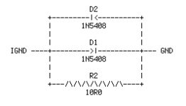
Here is the image of signal wiring of my amp. I use XLR input connectors, though inputs are single-ended. The reason is to utilize all the possibilities given by 10R R2 resistors between IGND and power GND. Both cables between preamp and amp and internal cables are shielded twisted pairs. Together with 10R resistors this arrangement yields excellent hum and EMI supression (see the review spectra), and no ground loops are created.
Pavel,
I am just at this Post #1093 (just half way though thread, gosh this in one long thread *panting* and this post must feel like it was made in "stone age" lol lol )
http://www.diyaudio.com/forums/showthread.php?postid=768933#post768933
of yours of 17th November 2005 13:11:03 as I read this very very long thread. I want to say the approach you are using for the wiring is very interesting. I am not an engineer, but for many years I have thought about using a shielded cable between units where the gound of the shield is only connected at one point. This way, as I am sure was part of your intent, one avoid ground loops between units while "extending" chassis ground for the cables. It never entered my mind to use a XLR connetor to faciliate this approach.
I applied this technique for the speaker cables of my modest Sinclair amplifier in late 1970s. I used a sheilded pair cable grounding the the shield to the chassis to remove the large signal being on the 15 floor and in line of sight of a local radio transmission tower in line of sight on top of a building due south about 4 blocks of the south suite I was in. The RFI filters the government communications licencing body were not effective. I could prove the cause was speaker cable were acting as an antenna by disconnecting and listening via headphones. The shielding of the speaker cable was very effective to the RFI issue. The cables only had to run about 5 feet from the amp to speakers. Clearly the 3-4 blocks, being line of sight, south end so could see transmission antenna of local radio station and I am sure the transmission power were all strong factors to the problem. I never had a problem until I moved into this 15th floor suite. Previously I was about 1.5 miles away from this transmitter I new existed, but never really registered in my mind.
About 10+ of years back I actually used a similar approach to your noted cabling for a antenna amplifier. It was to a very well known company that did not seem to properly amplify the antenna signal before the receiver. When I open the antenna amplifier out of curiousty I discovered my horror the wiring from the coax chassis connecter near the transformer to the circuit used some cheap basic hook up wire. Two seperate loose wires, not twisted together, that passed about 1/4 inch along EF transformer lamiate and across in diangle fashion rear corner to oppsite front corner of the internal chassis. I could not believe it. My common sense, not being a EE, was this had to be replaced. I replaced these two hookup wires from the chassis coax connecter to the place where the hook up wires were connected to the circuit.
Oh my goodness I could not believe the difference. Now the antenna amplifier behaved as I expected as I used the frequency and +-gain control controls. Before the modification use of the controls had no predictive or logical result. Now these controls and the reason for the antenna amplifier actually made sense! The comapny was not the least interested in the issue nor what the solution was. Clearly I have never purchased any more of their products, which are also rudely overpriced. I cannot understand how a 8 inch coax cable is so much more costly given the high "boutique" "audiophile" prices and marketing this company does. Thank goodness for DIY.
I have a few questions if I may about your approach based on the cabling diagram:.
1) For Zin at the amplifier side, is this in addition to the input network of the amplifier, be it this amp design MikeB created and you have put in much time and effort to address the issues the 2SA1943/2SC5200 highlighted? I ask so I understand for any other amp, and MikeB's amp, I like to test your approach to. I know some input networks already have a shunting like resistance across the input before the filter network. I just do nto know if that is same as Zin.
2) Is the chassis mounted XLR ground pin 3 isolated from chassis with the XLR chassis mount connector?
3) I assume if the amp already has a 10R0 like resistor from signal to chassis (noisy) gound one does not need to add the 10R0 you have as well into the cabling?
4) I had been thinking of using active balanced input and output driving circuits more seriously over that past year? Do you have any thoughts on pros/cons of using an active balanced line compared to your approach?
Thanks for your efforts on the issues related to the 2SA1943/2SC5200. I am working on sourcing some parts still for quasi excellent NMOS350 design. As interm I happened to luck out on a box store was callring a stereo receiver that used a toroid and these same Toshiba parts with lots and lots of heatsinking. It idles and runs very cool even though I use a volume about 50% or tad more. Despite perhaps a few electrolytics in places they should not be the imaging, detail and dynamics seems amazing for $80.00 Canadian. As a result of this unique steal of am amplifier I also like to explore trying out MikeB's design after knowing about your Toshiba 2SA1943/2SC5200 variant about a month ago. Until a few days ago I had not checked the diyAudio thread link on your page. Likewise the time and effort you have made to sort out the issues specific to these specific Toshiba devices. I will may have some questions, but I need to read the rest of the thread first and hope my brain can at least know if the questions I might have been already answered.
So thanks to you, MikeB and all those that have contributed to this thread as well as for carlos staring the thread.
Regards,
John L. Males
Willowdale, Ontario
Canada
25 April 2006 18:35
P.S. My appologies in advance for any typo errors. If you cannot "decode" the typo or feel there is a typo (some typos are correctly type spelling but can be mix of wrong/omitted words) speak up and ask me to clarify. jlm
John,
thank you very much for your valuable post. Please let me thoroughly review it some 10 hours later, as I am being quite busy by my regular job now. I will answer your questions.
Regards,
Pavel Macura
thank you very much for your valuable post. Please let me thoroughly review it some 10 hours later, as I am being quite busy by my regular job now. I will answer your questions.
Regards,
Pavel Macura
Hi Pavel,
Thanks for your heads up posting you will get back to me about my questions. I am in no hurry, so if it is better for your busy schedule to answer in day, few days or week or so that is fine.
Regards,
John L. Males
Willowdale, Ontario
Canada
26 April 2006 06:33
Thanks for your heads up posting you will get back to me about my questions. I am in no hurry, so if it is better for your busy schedule to answer in day, few days or week or so that is fine.
Regards,
John L. Males
Willowdale, Ontario
Canada
26 April 2006 06:33
Hi John,
regarding your questions:
1) Zin is an input impedance of Mike's amp, no special network added. 10R (R2) resistor is also not added, this resistor is a part of my symasym amp, connected between IGND and GND (power ground) pins of the PCB.
2) XLR connector (pin convention 1 - GND, 2 - +IN, 3 - -IN) does not have any pin connected to chassis at power amp. Pin 1 serves as shield extension connection.
3) Yes, the 10R resistor is that on amp PCB, no resistor added. But I shunt it by 2 parallel reversed 1N5408 diodes to prevent DC failure in case of 10R resistor burnt.
4) True balanced input yields better common mode voltage rejection compared to the described approach, as there is an impedance mismatch here and the rejection is efficient for low frequencies only.
Regards,
Pavel
Hi Pavel,
Thanks so much for your reply.
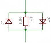
The shunting diodes you noted for answer to point (3) I liked. I cannot recall if I have seen this on some schematics I have seen. I will keep an eye out for the noted parallel reversed diode configuration. If I understand your description correctly this translates to the attachment below.
There are those that have no parallel reversed diodes seem to hold the opinion when R2 blows that is ok and provides protection to the amplifier. I am have a feeling you do not share that opinion. If so, when you have moment in few days, weeks or your time is not at such a preimum can you let me know if you do not share the noted opinion others have about R2, and is you do not share other's opinion for R2 provide a somewhat simple rational what happens in this circuit segment? Somewhat simple as I am not an EE by education nor in hobby, but I do understand electricity and basic (enough to be dangerous or observant ... lol lol) electronics.
Regards,
John L. Males
Willowdale, Ontario
Canada
27 April 2006 04:20
27 April 2006 04:43 Removed character based schematic examples for fixed and proportional fonts had all spaces deleted to one space rendering character version in message body useless 🙁 and replaced with simple graphic attachment.
Thanks so much for your reply.
The shunting diodes you noted for answer to point (3) I liked. I cannot recall if I have seen this on some schematics I have seen. I will keep an eye out for the noted parallel reversed diode configuration. If I understand your description correctly this translates to the attachment below.
There are those that have no parallel reversed diodes seem to hold the opinion when R2 blows that is ok and provides protection to the amplifier. I am have a feeling you do not share that opinion. If so, when you have moment in few days, weeks or your time is not at such a preimum can you let me know if you do not share the noted opinion others have about R2, and is you do not share other's opinion for R2 provide a somewhat simple rational what happens in this circuit segment? Somewhat simple as I am not an EE by education nor in hobby, but I do understand electricity and basic (enough to be dangerous or observant ... lol lol) electronics.
Regards,
John L. Males
Willowdale, Ontario
Canada
27 April 2006 04:20
27 April 2006 04:43 Removed character based schematic examples for fixed and proportional fonts had all spaces deleted to one space rendering character version in message body useless 🙁 and replaced with simple graphic attachment.
Attachments
There's now a new symasym working in Belgium. 🙂 It's only in between a portable cd player and a pair of cheap speakers for testing but it works perfectly.
I'll try to post some pictures when I get my hands on a digital camera. It's probably not the best looking symasym, it's simply housed in an old Dell computer case.
Specs :
- PMA's PCB,
- Supply rails of 29V under load,
- There is a total of 8 caps, 4700uF/63V, for the power supply, organised in two seperate supplies (thus 2 caps for each power rail),
- There's an integrated preamp inside, simply two opa2132 in unity gain with balance and volume control in between (both ALPS blue velvet). Two unbalanced inputs.
- Bias at 110mA,
- The heatsink are not huge (around 0.8C°/W) but get only a bit warm with music playing (6ohms speakers),
- Offset is under 5mV for each channel.
pc boards
HI
I would like to have a set of board , if some one has a spare set or planing to order now I would be intrested to .
Thanks
HI
I would like to have a set of board , if some one has a spare set or planing to order now I would be intrested to .
Thanks
Here's the ugly duck 😉 With my +/-29VDC rails, I guess I get around 50W in 6ohms.
I've been testing it in two configurations :
- with an old philips CD473 and a pair of Cabasse Sampan Leger (very nice vintage speakers, quite sensitive),
- modified philips cd723 and a pair of wharfedale 8.1 (86dB/W).
The amplifier was good on both systems. It is however a better match for the wharfies (even if they are certainly not as good as the cabasse in absolute terms). It has a very clean and sharp sound that grabs the little speakers (the cabasse asks for a slightly more romantic sound).
I think I'm gonna up the bias to see if I get any improvements, the heatsinks and output transistors are barely warm after an hour of rock at loud levels.
The amp is dead silent into the cabasse btw.
An externally hosted image should be here but it was not working when we last tested it.
An externally hosted image should be here but it was not working when we last tested it.
An externally hosted image should be here but it was not working when we last tested it.
I've been testing it in two configurations :
- with an old philips CD473 and a pair of Cabasse Sampan Leger (very nice vintage speakers, quite sensitive),
- modified philips cd723 and a pair of wharfedale 8.1 (86dB/W).
The amplifier was good on both systems. It is however a better match for the wharfies (even if they are certainly not as good as the cabasse in absolute terms). It has a very clean and sharp sound that grabs the little speakers (the cabasse asks for a slightly more romantic sound).
I think I'm gonna up the bias to see if I get any improvements, the heatsinks and output transistors are barely warm after an hour of rock at loud levels.
The amp is dead silent into the cabasse btw.
HI
These is my second try to find some help about these amplifier pc board. I already have some parts and transformers for these amplifier , but to start to build I realy need a good pc board.
At firts I started with the ESP mosfet amp but after I read about from diferent people diferent opinions I desided to go on and sell it and order a kit from Greg .
Now I found these project (more intresting)and I see many of you who built are satisfyed with I would rather give a try to these than the SKA. How I already mentioned I have some of the parts , power supply, enclosure ect.
I would like to ask if some one know from were I can order a par or maybe two pc board please let me know.
One more question if some one had the oportunity to listen ,or compare these two amp , the KSA and these .
Please guys I realy would apresseate any help with these project pc board
Thanks :
Gaborbela, maybe chuck911 can help you, he has/had a handful of pcbs...
http://www.diyaudio.com/forums/showthread.php?postid=859832#post859832
Or, are you familiar with etching pcbs yourself ?
Ben, nice to see your progress on the symasyms, i'm happy that you are pleased sofar ! 🙂
Btw, i don't remember, what outputdevices are you using ?
Mike
http://www.diyaudio.com/forums/showthread.php?postid=859832#post859832
Or, are you familiar with etching pcbs yourself ?
Ben, nice to see your progress on the symasyms, i'm happy that you are pleased sofar ! 🙂
Btw, i don't remember, what outputdevices are you using ?
Mike
The output devices are the MJL. I tried with more bias but the quality gain wasn't obvious (the system probably isn't resolving enough). It will run cooler, not a bad thing. Building is over, I'll just have to put knobs on the pots 😉
A big thank to Mike for the design and the advices during building. This is a very nice amp for those who don't want to spend tons of money and don't need tons of power. For the price of an entry level hifi amp, the symasym is delivering way more.
PS : And thanks to PMA for the boards too.
A big thank to Mike for the design and the advices during building. This is a very nice amp for those who don't want to spend tons of money and don't need tons of power. For the price of an entry level hifi amp, the symasym is delivering way more.
PS : And thanks to PMA for the boards too.
Regarding the boards - I had 4 pcs produced. I used 2 of them and sent 2 pcs to 00940, when he asked me.
The case is that it would be more expensive to produce only 2 boards now. And the overseas sale. I accept bank money transfer (wire transfer), which is quite reasonable in Europe, but high fee in US/Canada. The result is that I often have a lot of e-mails regarding PCBs and overseas customers usually resign without answer. It is time consuming, so I am not that much enchanted to offer 2 boards to Canada for now 😉 .
The case is that it would be more expensive to produce only 2 boards now. And the overseas sale. I accept bank money transfer (wire transfer), which is quite reasonable in Europe, but high fee in US/Canada. The result is that I often have a lot of e-mails regarding PCBs and overseas customers usually resign without answer. It is time consuming, so I am not that much enchanted to offer 2 boards to Canada for now 😉 .
Hi Mike,
I need to get my coffee in me before I post, so here is a copy of my post in the fake transistors thread.
You didn't happen to run these amps through RMAA to compare the different ouputs did you? Also, did you match the outputs and drivers? What I am wondering is how much device matching may have to do with the sound quality.
The first unit (ver 5.3) is almost ready for playing with. I am waiting for driver transistors. I may buy a bunch of polystyrene caps to relace the ceramics. My past experience leads me solidly towards these cap types. I can only find them in 50V. My input cap is 1 uF, 4u7 and 10uF both non-stock and expensive as sin!!
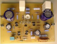
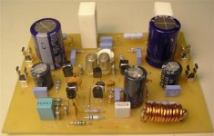
A shot of the board
-Chris
I need to get my coffee in me before I post, so here is a copy of my post in the fake transistors thread.
You didn't happen to run these amps through RMAA to compare the different ouputs did you? Also, did you match the outputs and drivers? What I am wondering is how much device matching may have to do with the sound quality.
The first unit (ver 5.3) is almost ready for playing with. I am waiting for driver transistors. I may buy a bunch of polystyrene caps to relace the ceramics. My past experience leads me solidly towards these cap types. I can only find them in 50V. My input cap is 1 uF, 4u7 and 10uF both non-stock and expensive as sin!!
A shot of the board
-Chris
Attachments
Hi Chris, i was too lazy to match these devices... The MJE15030/1 were not a problem, the ones i measured were very close in beta. The MJL21195/6 i tried should have been matched, my left channel shows DC of 5mv (was <3mv before), a good sign of extreme mismatch.
I did not take measurings, it's always a big rearranging of things.
The drivers (MJE15030/1) should be easy to get ? About the caps, you definitely hear the use of ceramic caps...
Mike
I did not take measurings, it's always a big rearranging of things.
The drivers (MJE15030/1) should be easy to get ? About the caps, you definitely hear the use of ceramic caps...
Mike
HI
Thanks for the answer for all of you .Yes you all right , to send money to Europe trou money wire it cost $48 it just not worth .I would preffer pay pal in that case or chash .
I found a company who can do the pc board for me and only $12 each , www.pcbex.com , .I conntact with them but they ask the Gerber file , I tryed to look at Mike site , yes is there but I can't open it .
I dont know why my computer does not open the File making pc boards .
I only can open at the PMA site , I sent those but these guy said is no good , he need the Gerber file .
At these point it look like I have to give up the project and try something else .I realy like these amp , it look simple to build and I have a lot of parts already , power supply , enclosure ect for it .
Any way thanks for the help for all of you .
Regards
Thanks for the answer for all of you .Yes you all right , to send money to Europe trou money wire it cost $48 it just not worth .I would preffer pay pal in that case or chash .
I found a company who can do the pc board for me and only $12 each , www.pcbex.com , .I conntact with them but they ask the Gerber file , I tryed to look at Mike site , yes is there but I can't open it .
I dont know why my computer does not open the File making pc boards .
I only can open at the PMA site , I sent those but these guy said is no good , he need the Gerber file .
At these point it look like I have to give up the project
and try something else .I realy like these amp , it look simple to build and I have a lot of parts already , power supply , enclosure ect for it .Any way thanks for the help for all of you .
Regards
You can get several free programs to view gerbers, but you might be alright just downloading them from Mike's site and sending them to the PCB house.
Guys, I keep looking at this project, and my bits pile, and I have everything in stock but the BD139s, how much fun would I have swapping them for MJE340s?
Guys, I keep looking at this project, and my bits pile, and I have everything in stock but the BD139s, how much fun would I have swapping them for MJE340s?
Hi Mike,
I could not bear to install the 330pF ceramics. Those would sound horrible in the Vas section.
Anyone know where I can buy 100V (or better) polystyrenes other than Partsconnexion? Radial would be good for Mike's board. Don't want to spend a fortune.
-Chris
Yes, I have mica caps as well (they don't fit the board). I want to change them one at a time to get my bearings on the sonics. I am putting a Mouser order together so I can buy some polystyrenes.About the caps, you definitely hear the use of ceramic caps...
I could not bear to install the 330pF ceramics. Those would sound horrible in the Vas section.
Anyone know where I can buy 100V (or better) polystyrenes other than Partsconnexion? Radial would be good for Mike's board. Don't want to spend a fortune.
Mine are back ordered on at least one of the pair. Figures.The MJE15030/1 were not a problem
-Chris
- Home
- Amplifiers
- Solid State
- Explendid amplifier designed by Michael Bittner, our MikeB