1 EUR = 1.40 CAD according to this currency converter
www.xe.com/ucc/convert.cgi
but why do you ask? He stated the price in dollars, presumably USD.
www.xe.com/ucc/convert.cgi
but why do you ask? He stated the price in dollars, presumably USD.
I can send you the hell adress...to catch the bode plotter Mike...because it is so
easy and confortable to adjust sensitivity using feedback resistor value...hehe....this way...maybe the bode plotter was send to hell in advance than the design it can make after modifications.
My Symassym 4 sounds great....even with sligtlhy differences from the original design.
The amplifier is less critical and less unstable than i use to read.
Well...i may be a lucky guy....or maybe...completelly deaf.....yeah...it is possible....more than 46 years listening amplifiers...maybe my ears are already damaged.
Time passes..... we all gonna face those things....long life with good ears to you Michael, as you produce nice designs.
regards,
Carlos
Yeah, the bode plotter... not to mistaken with body plotter... 😛
If you want to play with feedback network, you should add 33ohms emitter resistors to the input devices, this makes symasym unitygain stable. (In theory, not tested in realworld)
Mike
If you want to play with feedback network, you should add 33ohms emitter resistors to the input devices, this makes symasym unitygain stable. (In theory, not tested in realworld)
Mike
Hi Mike, you may have mentioned it already, what is minimum required VA rating for power transformer per channel? Thanks.
Chuck, Walda,
how nice to see you here 😉 .
Chuck, I believe for you to continue with technical help here, as I am very busy with my professional projects.
Regards,
Pavel
P.S. I can share experience with selling PCBs abroad, just send me an e-mail.
how nice to see you here 😉 .
Chuck, I believe for you to continue with technical help here, as I am very busy with my professional projects.
Regards,
Pavel
P.S. I can share experience with selling PCBs abroad, just send me an e-mail.
Hi Tim !
Are you going to drive 4 or 8ohm speakers ? I use a single 250VA (2*25v 5a) toroid for both channels into 4ohms. In theory this is already to small, but did not have that feeling. If you drive 8ohms, a 100va per channel should be enough. For 4ohms a 150 or 200va should do it.
If you use a single rectifier bridge per PSU, connect the AC-wires (creating a centertap) so that the other 2 wires going to the rectifier measure 50v (beeing in phase). This ensures a "symetric" ripple, giving a more silent powergnd, and gives less than half of ripple in the DC-supplylines. This is a quite important detail, but not often mentioned. If you follow this, i see no advantage in using 2 rectifiers per PSU.
Mike
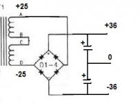
tttking said:Mike: Thanks for the reply. Is this what you mean ? (See picture attached)
Yes, sometimes it is not sure how the polarity of the 2nd winding is. In your drawing you are missing the groundconnection, B-C to GND.
Mike
Hi Mike,
Are you using more than two filter caps? CRC? What uf rating?
Right now on my bench I am using a pair of 22,000uf and I am seeing only 19mVAC on the rails and 39VDC. I have to get my ear right up to the tweet to hear even the slightest buzz. an It is all laying on th ebench with wires going every where.
Blessings, Terry
Hi Terry !
I use 2 BC-Caps, 22000uF 40v and a single metal bridge, 250v 25a rating. I have 2 RCs at AC side, 100nf+500ohms. I did not really realize a benefit from the RCs, according to sims these eliminate diode ringing. I need to do some scoping there.
When i press my ears to the tweeters and concentrate i perceive some noise, buzz or hum is below what i can hear. I have not measured the ripple yet...
Mike
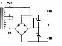
tttking said:Mike: Thank you for your patience. Does it look OK now?
Yes, perfect !

Mike
Hmmm, we might get into trouble with Anthony Holton ?
This schematic might look too much like his AV-series.
Mike
This schematic might look too much like his AV-series.
Mike
Hi dan.radu, these mosfet poweramps might be a good alternative, they share the same topology and are very high power.
They are sold as kits on www.aussieamplifiers.com, including nice PCBs. I heard that they are very good sounding amps.
Mike
They are sold as kits on www.aussieamplifiers.com, including nice PCBs. I heard that they are very good sounding amps.
Mike
Hi Guys,
I finished one of my Symasyms. It has the 5_3 boards. Sounds amazing to me. Anyway, here are some pics.


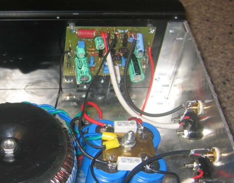
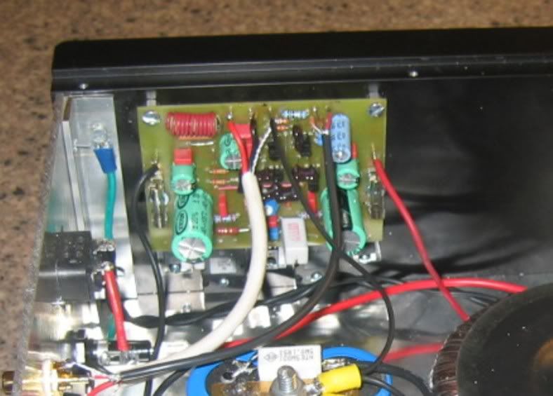
Let me know what you think. 😀
Blessings, Terry
I finished one of my Symasyms. It has the 5_3 boards. Sounds amazing to me. Anyway, here are some pics.
Let me know what you think. 😀
Blessings, Terry
still4given said:Let me know what you think. 😀
Blessings, Terry
You may have had some struggles with electron circulation on the initial boards, but it looks like the mechanical side is no problem for you. Very nice.
If you orient those fins vertically, you could get by using them only on the back half. Might not look quit as cool though. Given the surface area of the aluminum plate, if you don't play a lot at high volume and are driving 8 amp speakers, you might get by without the fins. Again, wouldn't look as cool.
Sheldon
wow still$given that looks really nice art
what did you use to cut the panels
very nice job, way to go dude!..
what did you use to cut the panels
very nice job, way to go dude!..
- Home
- Amplifiers
- Solid State
- Explendid amplifier designed by Michael Bittner, our MikeB