Re: PCB layout
Hi John,
Eagle does multi layers but is restricted to 2 in the free version.
I went though the same process as you, trying many packages, then I bit the bullet and concentrated on one, which happened to be Eagle.
The main issue to overcome is the creation of your libraries, you have to get quick at doing this because there always seems to be a component or two you can't find.
I haven't done that schematic but as you say it's a fairly common configuration. If my PC with Eagle was working, I'd offer to do the schematic, but that wouldn't really help you in the long run.
regards
jmateus said:Right now I think the best way is to stick to ONE and try to learn it, I do not see any other way.
By the way, is Eagle able to do ONLY one layer as you have done
for your Syma?
The schematic I'm trying to layout is a power amplifier published
in AUDIO ELECTRONICS number 3/99, author is José Arjol Acebal,
the amp is called Arjol professional amplifier. It's a common
configuration, and if I can post it there it is:
Hi John,
Eagle does multi layers but is restricted to 2 in the free version.
I went though the same process as you, trying many packages, then I bit the bullet and concentrated on one, which happened to be Eagle.
The main issue to overcome is the creation of your libraries, you have to get quick at doing this because there always seems to be a component or two you can't find.
I haven't done that schematic but as you say it's a fairly common configuration. If my PC with Eagle was working, I'd offer to do the schematic, but that wouldn't really help you in the long run.
regards
Ryssen:
The PCBs cost about U.S. $24 per set of two plus shipping. I have no idea how much the shipping is. I have no Paypal account. If you want to risk money(US $) in mail, please let me know. I will delay ordering till tomorrow morning 8:30 am Los Angeles time. Please let me know. It is now 7:43 pm Los Angeles time.
The PCBs cost about U.S. $24 per set of two plus shipping. I have no idea how much the shipping is. I have no Paypal account. If you want to risk money(US $) in mail, please let me know. I will delay ordering till tomorrow morning 8:30 am Los Angeles time. Please let me know. It is now 7:43 pm Los Angeles time.
Michael : thanks a lot for the grounding scheme. I've reworked my layout.
Regarding the supply. I've ten 4700uF/50V caps on hand but only one transformer. Would you use 4 caps per channel (left, right) or one single capacitor bank of ten caps for both channel ?
Further questions. How stable is the amp with some heavy capacitance at the output ? I'm using braided cat5 as speaker wire and capacitance is on the high side.
And finally, has the gain reduction any ill effect on the sound ?
Thanks a lot 🙂
Attachments
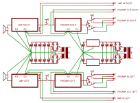
Hi Ben, do NOT connect Powergnd and Signalgnd, this will create problems and reduce quality. Connect the Speaker-GND to the amp, not the ground-star. Make it as simple as i have drawn. Use shielded cable for the signals, the shielding will connect the signal-gnds. Less is more, the more grounds you connect, the higher the risk of groundloops.
What do you mean with reduced gain ? Did you change the feedbacknetwork ? You must not do that, you risk oscillation and will reduce quality. Changing the feedbacknetwork creates a completely different bodeplot, moving the finetuning to hell.
I am not sure about the capacitors, a single bank with 2x4 4700uf should do it.
If you have the outputcoil the capacitive load should not create problems.
Mike
MikeB said:What do you mean with reduced gain ? Did you change the feedbacknetwork ? You must not do that, you risk oscillation and will reduce quality. Changing the feedbacknetwork creates a completely different bodeplot, moving the finetuning to hell.
I'm quoting your website :
If the gain is too high because symasym is driven from preamp, R30 can be increased from 499ohms to 1k, but in this case R16/19 (22 or 33 ohms, not on schematic, REs to Q1/2) are required to keep feedback at same level and symasym stable.
If i remember correct, you have symasym5_2, there was no option for R16/19. If you have these, this change is no problem.
Mike
Mike
Wrong page bookmarked 🙄 You're right. I suppose a fixed voltage divider at the input of the amp will work best then.
Maybe you should place this voltagedivider in front of the preamp ?
So you get the full low outputimpedance from the preamp to mainamp.
Mike
So you get the full low outputimpedance from the preamp to mainamp.
Mike
The preamp serves also as a headphone amp, so it's a bit hard to place the voltage divider before it. I'm gonna try without it at first. 
2 00940: Ben why are you using two bridge rectifier for one suply? This connection has larger Rout because curent must go through 2 diodes in each polarity. Rout is larger for one Rd of one useless diode in the rail.
tttking said:To Terry and Sheldon: PCBs ordered this morning, two weeks lead time.
Very cool! Do you need any money now or can I just pay you when I pick them up?
Blessings, Terry
Hi Guys,
I thought I had enough aluminum plate to build some cases but it turns out I didn't so I did some listening last night. I hooked up the 5_2 boards again and I can't hear any difference between them and the 5_3 boards. This is without a doubt the clearest, cleanest sounding amp I have heard to date. I believe it is even cleaner sounding than my Leach. Right now I have it all laying on my bench and I am just using one 25-0-25 400va transformer a single bridge and a pair of 28000uf caps for the PSU. Got it all connected with 22ga jumper wires with clips. I'm even using those small clip leads for the speakers and it is just clear as a bell.
I can't get over how cool the amp runs. I played it pretty loud for about 15 minutes and the outputs are only luke warm to the touch. I'm not sure I will ever build another Class A amp.
Someone needs to do a GB on this and get some professional boards made. This is too good to only be built by those who etch.
Blessings, Terry
tttking said:To Terry and Sheldon: PCBs ordered this morning, two weeks lead time.
e-mail me how you'd like payment, address info etc. sheldone"at" cox.net
Sheldon
00940: Ben The upper image is real only for very bad design of supply PCB. The caps of both rail in supply must be very close. In the well-designed supply PCB are these resistances much smaller than ESR of used caps. And that causes similar problems with voltage drops over ESR. As I say for good and dimensioning supply PCB this is...
I agre,I`m in for 2 boards.🙂Someone needs to do a GB on this and get some professional boards made. This is too good to only be built by those who etch.
Maybe let this idea sit until more reports come in. I'll be building a pair soon (thanks to Clem for assistance). There may be another in the offing soon as the higher power version is developed.
-Chris
-Chris
- Home
- Amplifiers
- Solid State
- Explendid amplifier designed by Michael Bittner, our MikeB