Terry and Sheldon:
If you are still interested in some PCBs for SYMASYM5.3, I am ready to send out the Gerber and Drill files to PCBEX - a PCB maker. The boards will have component side silk screen, green solder masks on both sides, an option of 1oz or 2oz copper. I am leaning toward 2oz. Again the cost is $10 per piece ($20 per set) plus shipping from PCBEX of $18 and packaging/postage from me to you at cost. The lead time is two weeks for the manucfacturer plus shipping time. Please let me know how many you want if any. I can also post the images and/or the Gerber and drills files if you are interested in looking at them before your decision. I apologize for the slight delay. I have been busy with other things lately.
If you are still interested in some PCBs for SYMASYM5.3, I am ready to send out the Gerber and Drill files to PCBEX - a PCB maker. The boards will have component side silk screen, green solder masks on both sides, an option of 1oz or 2oz copper. I am leaning toward 2oz. Again the cost is $10 per piece ($20 per set) plus shipping from PCBEX of $18 and packaging/postage from me to you at cost. The lead time is two weeks for the manucfacturer plus shipping time. Please let me know how many you want if any. I can also post the images and/or the Gerber and drills files if you are interested in looking at them before your decision. I apologize for the slight delay. I have been busy with other things lately.
symasym - memdist
Hi Mike!
I cannot refuse the feeling that such a good sonic results of your symasym are coming from cascoding the VAS too.
Instead of VAS symasym’s construction is rather standard. So maybe peufeu http://peufeu.free.fr/audio/memory/ was right that there is a need to project VAS in the way to minimize “memory distortion”?
One of the ways to minimize memdist is to cascode VAS transistors. In symasym’s case this is exactly used (in connection with classical amplification stages).
What do you think, is this too far similarity from memdist?
Hi Ben, I will answer you this evening, it will take some time...
Padamiecki, i don't think that the peufeu memdist does apply here, for this you need to have very constant dissipation in the active devices, a simple cascode would not do it, and only one of the active devices is cascoded. I added this cascode to keep average dissipation in both bjts for 2nd diffamp equal.
I personally believe that you don't need exotic topology to get good sonics, it is the finetuning. If you pay enough attention to the important details you get a good sounding amp.
Mike
MikeB said:If you pay enough attention to the important details you get a good sounding amp.

Another improvement step
Hello Mike and guys
Yesterday I tried to improve the Symasym by replacing the input
cap, I had in this latest one a polyester cap of 3.3 uf paralled
by another 1uf. Ok, I never thought a great deal about this
combination quality wise but this was what I had in my caps
bin.
When I say this amplifier works rather well with crappy parts
I mean it, Symasym performed excellent with thse caps at the
input.
But, allas, I had to do something else to the sound and so
I decided to do an experiment. Kind of came to my mind that
I had some polypropylene MKP caps from the times fiddling with
crossovers and that was it, looked for a 4.7 uf Solen/400 V
and installed one in each channel.
Results? Wow, what a difference, the sound opened even more
and apart from the aweful loooks of these two monsters, the
results are astonishing and I'm very happy to have decided to
do that. The looks are terrible looking but I don't care, the
amplifier is enclosed so nobody sees it.
Mainly the bass had a 45 % improvement and also the higher
frequencies, the sound stage opened up a little more. Would
all this be possible or is it my whole impression?
I thought I would share this with you guys.
Need some help
Hello fellow posters
I've been triyng to get a layout of a certain schematic using
three different free PCB programs. For some reason, including
my own ineffiency I can't do it, including what I thought would
be the esasiest one (Eagle) to use. I guess is too complicated
for me or on the other hand may be being free programs they are
not complete and won't do the job.
It is an amplifier that I want to translate into layout but either
I can't edit the complete schematic or if I do the program does
not get the layout.
To be honest with you guys I'm not at ease with these programs
(at all) and having tried three different ones I tend to think the
problem is me that doesn't know what to do.
Can anyone help me a bit in this endeavor?
I'd really appreciated.
Vgeorge:
I will be happy to help if you can arrange money transfer in US $ to me. I am not in business and do not know of any easy way to do so.
I will be happy to help if you can arrange money transfer in US $ to me. I am not in business and do not know of any easy way to do so.
Vgeorge:
I will be happy to help if you can arrange money transfer in US $ to me. I am not in business and do not know of any easy way to do so.
I will be happy to help if you can arrange money transfer in US $ to me. I am not in business and do not know of any easy way to do so.
tttking,
as I assume that you can' t take money through paypal, the cost of wire transfer to your account would cost as much as the boards themselves!
Thank you anyway, if I find another way, I' ll let you know, otherwise I will order some boards here.
as I assume that you can' t take money through paypal, the cost of wire transfer to your account would cost as much as the boards themselves!
Thank you anyway, if I find another way, I' ll let you know, otherwise I will order some boards here.
Hi Tim,
I only need two boards if that will be OK. I could probably pick up the boards from you since I work in the Los Angeles area.
Blessings, Terry
I only need two boards if that will be OK. I could probably pick up the boards from you since I work in the Los Angeles area.
Blessings, Terry
Terry and Sheldon:
I will order 8 boards tonight, 4 for Sheldon 2 for Terry and 2 for me.
Ryssen:
It is too hard to tranfer money to me. You may consider getting togather with Vgeorge to make some PCBs in Europe.
I will order 8 boards tonight, 4 for Sheldon 2 for Terry and 2 for me.
Ryssen:
It is too hard to tranfer money to me. You may consider getting togather with Vgeorge to make some PCBs in Europe.
Hi Ben !
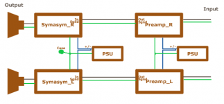
About the grounding scheme, you should not build it as you posted. Symasym has a signal-gnd input and through only that you should connect the preamp. Do you use a single supply for both channels ? And an extra supply for the preamp ? I assume that the preamp also has it's own signal-gnd. Also, only from the groundstar there should be a connection to the case, the RCA-jackets for input etc needs to be isolated from the case.
See my painting... Never connect signal-gnd and power-gnd. Use the supplied pins on the PCBs and use shielded cables for the signals (to preamp and from preamp to amp). Keep the 3 supply wires to the amps close together, the currents through these are zero in the sum, that means the magnetic field cancels itself.
I am not sure if you should connect the 2 groundstars, i think you shouldn't. You might connect them through a resistor, maybe 100ohms.
Mike
Attachments
Hi John, i have not much experience with coupling caps, but i often heard that they can have a big influence on sonic qualities. Maybe a paper/oil would be best choice ?
About PCB-layout programs, i also tried different and kept with eagle, it is not easy to understand, but it works. You have to try a lot and don't expect that the autorouter can do something good. You'll have to do it all by hand, placing parts and creating routes. Think of these programs like painting. After you have the schematic, you place the parts inside the white rect and connect manually the pads.
Mike
Thanks for that grounding scheme, Mike 
An incredible amount of work can go into a PCB layout. And manual revision is always recommended anyway...
An incredible amount of work can go into a PCB layout. And manual revision is always recommended anyway...
It is too hard to tranfer money to me. You may consider getting togather with Vgeorge to make some PCBs in Europe.
Money in an envelope?I have done that before.What aboat paypal?
If it doesnt work, vgorge tell me if you find anywhere to make them.
Hi John,
I recommend sticking with Eagle because the free version really only has one main restriction on the size of the board to 100 x 80 mm. Another important point is you can find a lot of schematics and PCBs to download from these forums ie, Symasym. 😀
I found the interface a little confusing, initially, because its not really windows compliant. Once I when through the following tutorial I was able to use it fine.
http://www.interq.or.jp/japan/se-inoue/e_eagle.htm
I have also found the Eagle news groups an excellent source of information. You will find you can do most things with combinations of [shift], [ctrl] and [alt] keys.
What schematic are you doing? I may have done one.
regards
PCB layout
Hi Mike
Yes, it's a real pain, not being able to do the routing...and sometimes not even the schematic with certain programs.
Of course I don't have any experience with this stuff most
often I don't even know what certain pull down menus want to tell me. This why I've been switching from Eagle to PCB 123,
Circad, you name it. And I keep telling myself It's got to be a program easier to deal with, but not, all of these offer more or less the same degree of difficulty.
Right now I think the best way is to stick to ONE and try to learn
it, I do not see any other way.
By the way, is Eagle able to do ONLY one layer as you have done
for your Syma?
Hello Greg
Yes, your'e right, all this involves a certain degree of difficulty as I said, besides it takes also a thing called persistance which I'm
not having too much these days. Oh well...
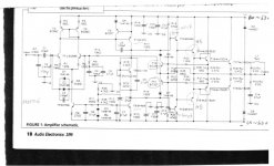
The schematic I'm trying to layout is a power amplifier published
in AUDIO ELECTRONICS number 3/99, author is José Arjol Acebal,
the amp is called Arjol professional amplifier. It's a common
configuration, and if I can post it there it is:
Hi Mike
Yes, it's a real pain, not being able to do the routing...and sometimes not even the schematic with certain programs.
Of course I don't have any experience with this stuff most
often I don't even know what certain pull down menus want to tell me. This why I've been switching from Eagle to PCB 123,
Circad, you name it. And I keep telling myself It's got to be a program easier to deal with, but not, all of these offer more or less the same degree of difficulty.
Right now I think the best way is to stick to ONE and try to learn
it, I do not see any other way.
By the way, is Eagle able to do ONLY one layer as you have done
for your Syma?
Hello Greg
Yes, your'e right, all this involves a certain degree of difficulty as I said, besides it takes also a thing called persistance which I'm
not having too much these days. Oh well...
The schematic I'm trying to layout is a power amplifier published
in AUDIO ELECTRONICS number 3/99, author is José Arjol Acebal,
the amp is called Arjol professional amplifier. It's a common
configuration, and if I can post it there it is:
Attachments
- Home
- Amplifiers
- Solid State
- Explendid amplifier designed by Michael Bittner, our MikeB