Hi Michael, i had to pay custom fee afterwards (handled by UPS) which is in fact the Mwst. Digikey itself had no taxes. Profusion has very reasonable prices, beeing in europe it might be best choice.
Mike
Mike
Hello Mike,
I solder the PSU; 4x ~25V/100VA (AC) with 2x 35V/4A (DC), each has 2x10.000uF/40 Caps. for every Power line.
One channel is now read to play.
I use 50mV over the two 0R22 resistors ==> ~113 mA in Class A/B.
The head sink will be around 25 °C cold(warm).
This "first" symasym v5.2 channel where yesterday the middle /center channel of my surround sound system from Denon AVR-1802.
Over Astra Satellite ii saw "Star Ship Enterprise" in Dolby Digital.
The two main channel where driven from a Elektor Mini Crescendo with ~ 50Watt/Cannel.
No hum..
I must finish the second cannel and the i can listen to my CD Player...
Thats all sofar.
MikeB said:
Uwe, have you already been able to listen to your symasyms ?
Mike
I solder the PSU; 4x ~25V/100VA (AC) with 2x 35V/4A (DC), each has 2x10.000uF/40 Caps. for every Power line.
One channel is now read to play.
I use 50mV over the two 0R22 resistors ==> ~113 mA in Class A/B.
The head sink will be around 25 °C cold(warm).
This "first" symasym v5.2 channel where yesterday the middle /center channel of my surround sound system from Denon AVR-1802.
Over Astra Satellite ii saw "Star Ship Enterprise" in Dolby Digital.
The two main channel where driven from a Elektor Mini Crescendo with ~ 50Watt/Cannel.
No hum..
I must finish the second cannel and the i can listen to my CD Player...
Thats all sofar.
Hi Guys,
I’m having a rough time getting my 5_3 boards working. I was getting close to + rail voltage on the outputs so I started by pulling the drivers. (15030/15031). That stopped the voltage at the output of course but I still see it at BD139. If I pull Q12 it goes away. So I replaced Q12 and it is still there. With 12,14VDC on the rails and with Q12 and Q4 pulled I read 11.98 at the emitter pad for Q12, 10.62VDC at the base and 0,00VDC at the collector. If I attach a new 2n5401 to the pads of Q12 I get E-11,86vdc, B-11,18 & C-11,86.
Can someone figure out what is going on from this? The other board is doing the same thing except on the negative rail. My 5_2 boards are playing fine. Just can’t seem to figure out what is wrong with the 5_3 boards.
Thanks, Terry
Hi Terry, it would be a pity to not get the v5.3 running, they are an improvement to v5.2...
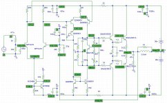
I need readings, start with R5/R6, they should show ~1v. If not, at least the sum of both must be 2v.
Across R10, you should read ~0.4v. R15/R17, you should read ~0.45v, or the sum should be ~0.9v.
Did you make the readings at q12 with the drivers pulled ? If yes, the problem is not in the outputstage.
It looks like the problem is somewhere at Q5/3/9/4.
Symasym5_3 is definitely functional, i am listening to it !
Have you verified that everywhere are the correct transistors ?
Oh, i just realized, having the drivers pulled out makes symasym operate openloop (no feedback), in this case you will get unpredictable voltage at vas output. The outputstage must be functional to get correct readings.
But, these sums of the voltages (R5/6 R15/17) are still valid.
Mike
Hi mikeB how you doin buddy
for vas i have found that some TELEFUNKEN transistors outperformed American ana Japanesse types do you know
of any other such types yourself from TELEFUNKEN
thanks in advance
cheers dude
for vas i have found that some TELEFUNKEN transistors outperformed American ana Japanesse types do you know
of any other such types yourself from TELEFUNKEN
thanks in advance
cheers dude
Hi Dx.Master
I use 50mV over the two 0R22 resistors ==> ~113 mA in Class A/B.
The head sink will be around 25 °C cold(warm).
This bias seems considerably too much. According to Mike the
right bias for this amplifier in class AB is at the most 10 mV over
the 0.22 resistors what gives around 22 mA of current.
With this high bias how are your drivers and outputs, running
hot after a while?
Hello jmateus,
this a second account on a other pc, so i use: op220fz and Dx.Master on the other.
My head sink will be only hand warm - cold !
I have a Elektor Mini Crescendo with Bias 0,2A at 44V each rail.
80mV over 2x 0,2 Ohm.
These are 17,6 Watt Power.
So i want test and check the temp on both AMPs.
My symasym v5.2 has with 2x35V Rail and after warm up 43mV; then i use 97,7 mA Bias.
This are only 6,8 Watt Power and i have fun ...
PMA use 150mA i think?

this a second account on a other pc, so i use: op220fz and Dx.Master on the other.
jmateus said:Hi Dx.Master
I use 50mV over the two 0R22 resistors ==> ~113 mA in Class A/B.
The head sink will be around 25 °C cold(warm).
This bias seems considerably too much. According to Mike the
right bias for this amplifier in class AB is at the most 10 mV over
the 0.22 resistors what gives around 22 mA of current.
With this high bias how are your drivers and outputs, running
hot after a while?
My head sink will be only hand warm - cold !
I have a Elektor Mini Crescendo with Bias 0,2A at 44V each rail.
80mV over 2x 0,2 Ohm.
These are 17,6 Watt Power.
So i want test and check the temp on both AMPs.
My symasym v5.2 has with 2x35V Rail and after warm up 43mV; then i use 97,7 mA Bias.
This are only 6,8 Watt Power and i have fun ...
PMA use 150mA i think?
Hi Mike,
I am making my own 5.3 boards with PCBexpress software.
I am too lazy to deal with etching my own pcbs I guess.
I made a few mods, primarily concerned with fitting the MT200. I also made a couple of different provisions for grounding:
1- the original scheme
2- with the 10ohms after the whole input/vas grounding (except the bypass which I kept routed the way you had them.
3- I added a different bias option for the ccs. basically I have the 2x22k resistors after the first original resistor I can either go to gnd, go to gnd with a 10uf cap and go to the positive rail with the second 22k resistor.
4-I inverted the position of the drivers and the power trannies
5-moved the RL and zobel network up closer to the power transistors.
It is not clear to me wether the 22 ohms in the diff pair are used or not, they are there in the PCB but out in the schematic.
I am not quite done yet but I will post the layout.
Hi John, my recommended bias was 24mv over both 0.22ohms, giving 55ma.
Uwe, for symasym5_2 it is better to have "high" bias to reduce the induced even harmonics caused by ClassB operation (caused by grounding). That was the reason why Pavel used the higher bias.
Grataku, the 22ohms in the input diffamp are not used, they are reserved. They will be necessary if overall gain needs to be reduced, to keep global feedback factor unchanged. And i wanted to keep the possibility for them to experiment... If you take a look on my webpage, on the photo of my version you see that they are skipped with small wires. For improving psrr in the ccs, the cap needs to go to negative rail. Look at the symasym6, i used this cap for the ccs there. (simply ignore the cascode)
Mike
Biasing the symasym
Hi Mike
That's about right, I was talking about 10 to 12 mV over ONE
0.22 resistor, consequently 20~24 mV over two resistors.
Checks!
Hi Mike
That's about right, I was talking about 10 to 12 mV over ONE
0.22 resistor, consequently 20~24 mV over two resistors.
Checks!
R16/R19 if I read correctly... did'nt have these? Then I'm fine I guess 🙂 Have to look when I get home again.
MikeB said:Hi Terry, it would be a pity to not get the v5.3 running, they are an improvement to v5.2...
I need readings, start with R5/R6, they should show ~1v. If not, at least the sum of both must be 2v.
Across R10, you should read ~0.4v. R15/R17, you should read ~0.45v, or the sum should be ~0.9v.
Did you make the readings at q12 with the drivers pulled ? If yes, the problem is not in the outputstage.
It looks like the problem is somewhere at Q5/3/9/4.
Symasym5_3 is definitely functional, i am listening to it !
Have you verified that everywhere are the correct transistors ?
Oh, i just realized, having the drivers pulled out makes symasym operate openloop (no feedback), in this case you will get unpredictable voltage at vas output. The outputstage must be functional to get correct readings.
But, these sums of the voltages (R5/6 R15/17) are still valid.
Mike
Hi Mike,
Thanks so much for thaking the time to help me.
Here's what I did with one board. I haven't had time to tackle the other yet. I installed new 2N5401's. I reinstalled the drivers after checking them to be good. I am no longer getting rail voltage at the output but I still have something out of balance. I used the chart below that someone posted. I used my variac to set the rail voltage to +/-36VDC. Everything checks out pretty well except that if I adjust the bias pot so that I am reading -.589VDC on the base of MJL1302, I only have .334VDC at the base of the MJL3281. Also, the lowest reading I can get across the 0R22 output emitter resistor on the -side is 170mV. Before I can get to 12mV on the + side emitter resistor, the -side is over 500mV. Even with the weird off balance I only read 10mV offset on the output. At least I getting closer. I hasd a feeling that the feedback circuit was playing into it. I wish I understood this stuff better so I didn't keep bothering you guys with it. Hopefully others are learning something from my mistakes.

Thanks again, Terry
Attachments
Terry, have you verified that the emitter resistor on - side is really 0R22 ? You might have a cold solder here, or the resistor burned ? Sounds like you have 10ohms here. You should check the whole outputstage here.
Mike
Mike
Hi Mike,
Ok I'll check that. I could just replace the whole side. I need to switch out the MJW's for MJL's anyway. Might as well replace the driver and emitter resistor while I'm at it. Hopefuly that will get things straightened out.
Thanks, Terry
Ok I'll check that. I could just replace the whole side. I need to switch out the MJW's for MJL's anyway. Might as well replace the driver and emitter resistor while I'm at it. Hopefuly that will get things straightened out.
Thanks, Terry
BTW Mike, the "jumper" library contains wire jumpers. But you have to put them into the schematic too, and I'm not 100% sure if EAGLE gets the ratsnest right, I had some little problems with it.
It didn't, part of the program realized that the voltage nodes are identical, others not. My frust was gone at once when i used the upper layer. Maybe newer version work better...
Mike
Mike
MikeB, some questions about the Symaym5.3 BRD file before I send it to the PCB maker. What are those "pad"s on the component layer for? What is the purpose of the third layer with a square at the outline of the board and four circles at mounting points for? Thanks again.
- Home
- Amplifiers
- Solid State
- Explendid amplifier designed by Michael Bittner, our MikeB