anatech said:Hi Mike,
I would definitely prototype without protection. Fuses would be in order in case something goes bang until the design is more stable.
I am thinking it might be easier to design for a higher voltage and start running it at +- 50VDC. Increase until things get too warm. That way you can find the safest higher power for that design. That will determine the number of outputs too.
Any advantage to going to MJ21195 / 6 devices? The TO-3 may help with heat.
-Chris
I would like to keep the fast devices... My concern was mainly about SOA, as the amp is still ClassAB, at least idle dissipation is no problem. The cascodes will dissipate 400mw, too much for a to92 (for my taste), but no problem for a to126 with smallish heatsinks.
With 3 pairs a full scale sinewave into 4ohms will dissipate ~30watts per device. TO264 should be able to handle 60watts.
Upupa Epops said:It is superstition, guys.... correct designed protection circuit have any impact to sound... 😉
Upupa, i just wanted to spare the work for protection until i know if this circuit does sound good.
But, i might need help with protection circuit...
Mike
Best device for VAS are 2 SA 1540 ( 1541 ) and 2 SC 3955 ( 3956 ), made by Sanyo... They have ft 300 Mhz and Ptot 7 W and high Vceo.... And about protection : ask Mikeks, he's expert at this field... 😉
To save others a little time, here is a few links to the datasheets mentioned.
http://www.datasheet4u.com/search.php
From Upupa Epops:
2SC2547:
http://www.datasheet4u.com/html/2/S/C/2SC2547_HitachiSemiconductor.pdf.html
From Christer:
2SA1209/2SC2911:
http://www.datasheet4u.com/html/2/S/C/2SC2911_SanyoSemiconDevice.pdf.html
From Upupa Epops:
2SA1540/2SC3955:
http://www.datasheet4u.com/html/2/S/C/2SC3955_SanyoSemiconDevice.pdf.html
2SA1541/2SC3956:
http://www.datasheet4u.com/html/2/S/A/2SA1541_SanyoSemiconDevice.pdf.html
regards
Mike,
While you wait for the MJL0281, why don't you consider the NJL3281?
They have the same good retention of hfe at high currents, and are slightly more powerful.
Joseph
I am looking forward to the MJL0281/0302, looks very promising and this time they got models that are functional...
While you wait for the MJL0281, why don't you consider the NJL3281?
They have the same good retention of hfe at high currents, and are slightly more powerful.
Joseph
Joseph Hynes
"While you wait for the MJL0281, why don't you consider the NJL3281?"
is the njl3281 type japo where can i get more info on it, thanks
for letting us know we appreciate it
regards
"While you wait for the MJL0281, why don't you consider the NJL3281?"
is the njl3281 type japo where can i get more info on it, thanks
for letting us know we appreciate it
regards
Hello MikeB,
for these device i found in NL: http://www.bmm-electronics.nl/
I have a nice person in NL and he can ship it to us too.
greetings
- you know - uwe (dx.master) from Germany.
for these device i found in NL: http://www.bmm-electronics.nl/
I have a nice person in NL and he can ship it to us too.
greetings
- you know - uwe (dx.master) from Germany.
Upupa Epops said:Best device for VAS are 2 SA 1540 ( 1541 ) and 2 SC 3955 ( 3956 ), made by Sanyo... They have ft 300 Mhz and Ptot 7 W and high Vceo.... And about protection : ask Mikeks, he's expert at this field... 😉
NJL3281D/NJL1302D datasheet:
http://www.datasheet4u.com/html/N/J/L/NJL3281D_ONSemiconductor.pdf.html
http://www.datasheet4u.com/html/N/J/L/NJL3281D_ONSemiconductor.pdf.html
MikeB said:Yes, this time i might not get away without some protection circuitry... 🙁 But i will make first prototype without, maybe it does not sound good...
What do you think, 50v supply for a more reasonable one ?
I could make 2 board versions, one with 2 pairs, and one with 4 or 5 ?
Mike
Hi Mike,
the circuit starts to look very close to the 200 W elektor project. Why re-invent the wheel? Why not start off simulating their input circuit? It uses +/- 68V regulated for the input section, Vreg that is, so each driver board is equipped with a pair of voltage regulator. That makes for a big board.
It uses cascoded jfets for the input diff and some weird looking, and discontinued, philips bf869,870 for the second differential which have very low 2 pF feedback capacity (? from the philips catalog).
I can email you the schematic. Let me know if you need it.
Hi MikeB, after reading most of the posts on symasym, I start to think that I will miss out on one of the best sounding amp ever, if I do not build one for myself. I am currently using a DOZ and am pretty happy with the sound. Would you please shad some lights on whether moving to SYMASYMA5 would be a significantly step forward? In your personal opinion of course! Also, how many watts do you think it produces when biased into class A at about 170ma as Carlos has done? Thank you, Carlos and all the other experts here for starting such a wonderful thing. I fully enjoy the discussion here, though I do not have enough knowledge to follow most of the technical details.
Now i am using two separated supplies, one for input stages,with 40 volts and other
for output stages, with standard voltage.
As Michael did not agreed with 180 ohms rails resistor, i made it this way, and resulted even better.
Symassym is a great amplifier...pleasant machine!
regards,
Carlos
for output stages, with standard voltage.
As Michael did not agreed with 180 ohms rails resistor, i made it this way, and resulted even better.
Symassym is a great amplifier...pleasant machine!
regards,
Carlos
Now, some guys that misunderstood my movements, may understand why i do some strange
Things.
Michael is very clever, a superior Intelectual Quocient than average people...well, at least i am sure he can kick my intelligence easy.
But everyman has some week point....his weekness is that he is extremelly competitive....the Aksa shown was the final "shot" to his decision to construct bigger Symassym.
Not only because of that, as many important guys, alike Mr. John and others asked this to him.
Also because natural development for powerholics.
Well, Hugh is preparing 350 watts unit...so.... before this new year of 2006 ends, i am sure Michael will be showing a bigger one...maybe 1 Kilowatt unit, as he design those things in 15 minutes, so skilled he is.
When finished the Hugh prototype, i will came into provocation...ahahahahaha....let's say, some stimulation...some aid to Michael's creativity.
Germans are incredible, reason why i respect them very much.
Maybe now, someone of you, in special Mr. John, can understand the reasons..... and another one, will be shown...near future.... a little bit bigger than Symassym...ahahahahaha!
The honorable King of Germania and Surroundings will not lost his crowd!
regards,
Carlos
I went through the prepared high power symasym version, posted by Michael here. IMHO this is just a 1st shot. I am sure that a lot of work still has to be done to make this version viable and reliable.
Hi Tim, don't get me wrong, the DoZ is a very good/pleasant sounding amp, in fact it was some kind of reference for me... 😉 The symasym sounds quite different compared to the doz. The biggest weakness of the doz is the bass, at least for me as i have big vented speakers, it is loose and unprecise. The symasym with it's ugly high damping factor and quite high psrr gives you a tight controlled and agressive bass with much punch. The midrange (voices) is at the same level, but the topend is different, symasym gives you much more transparency, clarity and details. The details delivered from symasm are unbelievable, micro reverbs, lips and tongues from singers, mechanical noises from instruments (vents/claps/airflow for example) are easily perceived. Where the doz sounds colorized, the symasym is completely natural. Also, the symasym shows more intense dynamics. And you have lot more power with much less heat... You can say, the doz sounds very nice, the symasym very accurate but also pleasant.
This description is for symasym5_3 with Toshibas as output devices, biased with 55ma. You might be surprised by the difference !
The bias does not change the outputpower, into 8 ohms 170ma bias only gives ~115mw ClassA-watts. With 36v supply output power is ~60watts into 8ohm, ~100watts into 4 ohm.
Carlos, i realized your manipulation after i posted the preview of the high power... Mostly i called your bluff earlier... :bawl:
You are right, with separated supplies for frontend and outputstage, you get rid of any effect regarding this rail resistor. In symasym6, i changed that and that resistor should have much less influence.
I don't need 15 minutes for a circuit, it took me at least a whole day...
Grataku, that's me, reinventing the wheel... As i have already done the critical fine tuning i will keep it except some details. The mpsa18 has ~1.2pf cob, is low noise, hfe of ~1000,ft >200mhz at 1.5ma, a quite perfect device for input-ltp i think.
Pavel, yes the schematic is a preview, the necessary changes are mje15032/33 as driver, adequate devices for the cascodes, replacement of the 2v-voltage sources, and maybe changing the cascoding for the ccs. This cascode might also need a basestopper. Sadly sims do not easily show parasitic oscillations. I also still have to determine necessary count of outputpairs. I hope that this amp does not get noisy with all these cascodes...
If you see other flaws (except missing protection) please tell me, we can do that by email...
I already verified clipping behaviour, bode plot, step response. The bodeplot telled gain margin of ~11db, phase margin of 110°. Step response showed only minimal internal ringing/overshoot.
Joseph, AFAIK the njl3281 is electrically identical to the mjl3281, but has the built in compensation diode. The MJL0281 is brand new, and seems to be onsemi's answer to the Toshibas. It shows enhanced linearity, improved speed, and excellent complementary match.
Mike
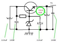
Please Pavel, an information, do you think that too much big condensers to rail
filtering can create some problem to sound reproduction?
I will explain...i prepared two transformers to Symassym, the higher voltage unit is beeing used to input stages, and an electronic filtering is used....those standards transistor, resistor and zener simple series filtering...... alike capacitance multiplier,or electronic voltage reducer.
I was in doubt related the electrolitic condenser to use at this circuit output....i decided to use only 220uF.
What do you think?
If i installed there, for instance, 10000uF....do you think that can create some problem....have i to snuberize...well, those CarlosFM circuits?
Hey Mike!....ahahaha!...manipulation is John's prefered term...let's say induction, or stimulation...or...let's say suggestion.... manipulation is too much Psycho....i hate Psycho!
regards,
Carlos
Attachments
Hi DestroyerX,
I will put that circuit to work in my version of the low power symasym for the input stage PS in place of the resistor. I would say that in the higher power version that is even more necessary IMO.
If that is a series regulator I often see a resistor from the rail to the cap to bring up the voltage a little more gradually. I prefer to use a mosfet as the active device. I have a few left.
Don't get too crazy tonite eh? 😉 😀
I am already Red because of Wine...humm...i love Wine with honey
Lovely.....hummmm
Cheers for all of you.
Happy new year to everyone!
regards, hic!
Carlos
Lovely.....hummmm
Cheers for all of you.
Happy new year to everyone!
regards, hic!
Carlos
High Sym amplifier
Hi Mike
Did I baptize the new amplifier as High Sym? Probably, but that
depends on you.
Just to tell you that this is a very good idea, to make the PCB
with provision for 2, 3 or 4 pairs of outputs, this way if I don't
feel like having 250W or a zillion watts, I'll settle for a simple
150W.
A hell of an idea!
Please e-mail me, I lost your adress because of a computer crash
the second in a month's time.....Putz!
Carlos,
I would probably not use a capacitor as big as 10000uF in that active filter output. If yes, then I would place a reverse polarised diode accross the regulating transistor, to prevent its damage after voltage turn-off.
I would probably not use a capacitor as big as 10000uF in that active filter output. If yes, then I would place a reverse polarised diode accross the regulating transistor, to prevent its damage after voltage turn-off.
- Home
- Amplifiers
- Solid State
- Explendid amplifier designed by Michael Bittner, our MikeB