qsc,crown,crest ........
ok carlos, you have definately hit the nail by the head, it is not possible to be an all rounder in audio electronics and I am still a learner in amp-building, just as smps and dc/ac inverters, horn loudspeakers etc. One thing I know is that a stupid question may bring about a radical change in audio at times.
I have seen some schematics of qsc,crown,crest,pssaudio etc, most of these amps have two channels each and are joined together by one or two components so that they always have one-amp with two channels.
That is my question.
www.qscaudio.com/support/ technical_support/schematics.htm - 9k
www.crownaudio.com/gen_htm/legacy/legacamp.htm - 53k
Pls I need a good site where I can download a lot on amp constructions.
That is the theory etc.
segun
Happy we are Segun, as we all have things to learn, and this is pleasant
May be boering the ones that already studied everything... they may feel lonely....as no one will understand what they mean...lonelyness is alike a prison.
We have all this world of things to understand, to learn...i am happy that i am deeply ignorant related many things.
Now i am crazy to learn french...and to learn how to use better my computer PC scope.
I also learned, last days, that pride is an enormous foolish...only create problems to our short life in this earth...we are passengers here..let's have fun!
I suggest you to read all forum...jumping over discussions you will have wonderfull schematics, informs, evaluations.... no place better than our forum.
I am thinking to read entire forum again.
regards,
Carlos
Hi Carlos,
If nothing else, that will keep you very busy. There is so much material here it's scary. There is every chance you will learn a lot.
-Chris
If nothing else, that will keep you very busy. There is so much material here it's scary. There is every chance you will learn a lot.
-Chris
I will see dictionary Chris....Scary!..never heard...but seems not to be good
hehe....have some sound strange....junk?
regards,
Carlos
hehe....have some sound strange....junk?
regards,
Carlos
Hi Carlos,
Sorry, scary = frightening. As in too much information.
-Chris
Edit: still can't spell worth a darm.
Sorry, scary = frightening. As in too much information.
-Chris
Edit: still can't spell worth a darm.
About speakers impedance...
Hi Carlos.
You can have a nice graph of impedance vs frequency for your speaker IF, in the schematics you posted above (resistor in series with speaker),
a) as an amplifier you put your sound card output
b) you take the voltage drop at the resistor and feed it into your audio card input
c) then some software that analyses frequency response (Rightmark Audio Analyzer is suitable) will give you the graph (reversed) of the impedance vs frequency.
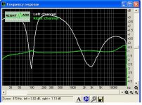
In the following picture the graph for my small bookshelf JPW speakers is the white line. You see that the minimum impedance is at around 250 Hz (because the graph is inverted) .
If you want to find how much exactly is the minimum impedance, feed your circuit (resistor+speaker in series) with a signal at that frequency (250 Hz in my case) and measure voltages across known resistor and speaker. Using Ohm's law it is easy to calculate. In my case the minimum resistance was about 6.4 Ohm (speaker says 6 Ohms, so it is quite close.)
Keep well....
(and sorry for the off-topic).
Hi Carlos.
You can have a nice graph of impedance vs frequency for your speaker IF, in the schematics you posted above (resistor in series with speaker),
a) as an amplifier you put your sound card output
b) you take the voltage drop at the resistor and feed it into your audio card input
c) then some software that analyses frequency response (Rightmark Audio Analyzer is suitable) will give you the graph (reversed) of the impedance vs frequency.
In the following picture the graph for my small bookshelf JPW speakers is the white line. You see that the minimum impedance is at around 250 Hz (because the graph is inverted) .
If you want to find how much exactly is the minimum impedance, feed your circuit (resistor+speaker in series) with a signal at that frequency (250 Hz in my case) and measure voltages across known resistor and speaker. Using Ohm's law it is easy to calculate. In my case the minimum resistance was about 6.4 Ohm (speaker says 6 Ohms, so it is quite close.)
Keep well....
(and sorry for the off-topic).
Attachments
It is nothing unusual to see speakers with very low impedance drops. Wilson Audio Maxx, though denoted as 8 Ohms, fails to 2.2 Ohms somewhere at 250Hz. Similar impedance drop is for BW Matrix 801, Thiel CS 3.6 and many other.
Speaker impedance is often a beast.
Speaker impedance is often a beast.
With suitable impedance correction and properly designed crossovers, there is no good reason for this. At the upper end I've seen speaker impedance rise to over 40 ohms at higher frequencies; these variations and phase shifts play merry hell with global nfb amps, and can destabilise them severely. Many of the problems of amp/speaker combinations come back to poor design of the crossover with wild deviations in impedance. When you hear a salesman say, 'This speaker is so good you really have to be careful with the choice of amplifier', it should ring alarm bells. Surprisingly, many of the top brands do not have well designed crossovers; they are designed to deliver the designers 'house sound', but often the electrical considerations are so badly done they need very large amps to cope. This is not good design, and is, in my view, unforgiveable. The so-called current dump amps can cover over these cracks, of course, but only at the expense of output circuitry designed like an arc welder and about as sonically pleasing.....
Cheers,
Hugh
Cheers,
Hugh
Good Dimitris Trifonopoulos, Pavel Macura and Hugh Dean
All informs complementary and very good to me.
So, i can understand, that having so enormous impedance variation (Dtriff graphic) and beeing so damned (Pavel opinnion), and Hugh Dean telling that the proper crossover design can be good, maybe protective.
May i deduce that we have to introduce inductances,capacitances and resistances to compensate speaker impedance variations.
I am imagining, Hugh, as i never could never observe your crossovers, only observing some industrial units, and i could even see ferrite used inside coils (terrible saturation!), well...i can imagine that those "ready to use" crossovers are not good to use, as each one may be done to his own matched speaker... and usually people (here) do not buy matched crossovers....are more frequency dividers than really crossovers...as only blocks bass when in series related the speakers drivers.
I am imagining that a good crossover may be dense in parts numbers...many coils, hi wattage resistors, some capacitors...
Am i rigth?..... sorry to be a little of topic, but give a small break in main subject to show me one crossover example, please.
I need only one schematic.... to have an idea of how complex, or not, are those "matched circuits"...or matching circuits....all rigth, crossover circuits.... and them we will continue with main topic.
regards,
Carlos
Hi Hugh,
From long experience in the audio field, I'll back you 100% on those view points. And yes, those designers ought to know better.
-Chris
From long experience in the audio field, I'll back you 100% on those view points. And yes, those designers ought to know better.
-Chris

I have the boards produced, and will show them in the evening (european time). This way I can guarantee that production files I posted here and on my web are correct.
I cannot wait your valuable evaluation...will be helpfull in many ways
Counting hours and minutes to have your opinnion.
Experienced guys alike you, evaluating...is a gift for us.
Congratulations will produce enormous pleasure
Criticisms will make us go deep into correction.
regards,
Carlos
Counting hours and minutes to have your opinnion.
Experienced guys alike you, evaluating...is a gift for us.
Congratulations will produce enormous pleasure
Criticisms will make us go deep into correction.
regards,
Carlos
Carlos,
thank you very much. The PCB scan is attached. Unfortunately I am so busy now, several different tasks must be solved. I hope to build and check these cute amps in a week or two.
Cheers,
Pavel
P.S. The more work we have to do, the more we are able to do.
thank you very much. The PCB scan is attached. Unfortunately I am so busy now, several different tasks must be solved. I hope to build and check these cute amps in a week or two.
Cheers,
Pavel
P.S. The more work we have to do, the more we are able to do.
Attachments

Pavel, looks great ! Where do you let your boards get produced ?
Pity that you are too busy at the moment...
Mike
Pity that you are too busy at the moment...
Mike
Could someone give me the dimensions of the PCB so that I could resize it correctly? I viewed it with Paint Shop Pro, but the printout is a full A4 page. Nice, but a problem for the components. I would like to try to build this design.🙂
johnnyx said:Could someone give me the dimensions of the PCB so that I could resize it correctly? I viewed it with Paint Shop Pro, but the printout is a full A4 page. Nice, but a problem for the components. I would like to try to build this design.🙂
Pavel's got a b&w .bmp for the board on his site.
Take
- Home
- Amplifiers
- Solid State
- Explendid amplifier designed by Michael Bittner, our MikeB