Hi Chris,
thanks for the advise! I will order some pairs of the MJL21193/94 - these are available at Mouser. The Toshiba´s are on their way, too - think I will build 2 channels with these ones as well - will post my findings here in a few weeks
thanks for the advise! I will order some pairs of the MJL21193/94 - these are available at Mouser. The Toshiba´s are on their way, too - think I will build 2 channels with these ones as well - will post my findings here in a few weeks
Alternative Drivers & Outputs. Also, is this PCB/Schematic "Good"/"Correct"?
Two Questions:
#1. Is it ok if I use genuine Toshiba TTC004B/TTA004B along with genuine Toshiba 2SC5200N/2SA1943N (all from Mouser) in the attached eBay "Classic Symasym5-3"? My alternative would be genuine Sanken MN130S/MP130S and Toshiba 2SC5171/2SA1930 taken from a disassembled receiver.
I ask in case it would be unstable and/or degraded. I could wait until my next Mouser order if necessary but I like to recycle when it makes sense.
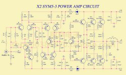
#2. Is the attached version (PCB and Schematic) "good"? I ask since I have seen a number of eBay kits or bare PCB where the layouts and/or actual schematics were poor and/or simplified and departed from the real thing. Also my eyes might be shot for the day but I don't see D1 & D2 on the PCB. (D1 & D2 are not needed, correct? What was the reason for them?)
Two Questions:
#1. Is it ok if I use genuine Toshiba TTC004B/TTA004B along with genuine Toshiba 2SC5200N/2SA1943N (all from Mouser) in the attached eBay "Classic Symasym5-3"? My alternative would be genuine Sanken MN130S/MP130S and Toshiba 2SC5171/2SA1930 taken from a disassembled receiver.
I ask in case it would be unstable and/or degraded. I could wait until my next Mouser order if necessary but I like to recycle when it makes sense.
#2. Is the attached version (PCB and Schematic) "good"? I ask since I have seen a number of eBay kits or bare PCB where the layouts and/or actual schematics were poor and/or simplified and departed from the real thing. Also my eyes might be shot for the day but I don't see D1 & D2 on the PCB. (D1 & D2 are not needed, correct? What was the reason for them?)
Attachments

Last edited:
Hi jxdking,
I don't think it is proper or reasonable to offer modifications to a working design based solely on a simulator run. This is especially true when your advice is to a person who is actively building one
Excellent advice as ever from Chris
Hi piggybladder,
Thank you ...
Hi kozard,
It's been a very long time on this one. I think 5.3 was the latest one, so find that schematic here and follow it. Every version 5 release was excellent, they all worked well. Beats the heck out of guessing or using questionable information.
Thank you ...
Hi kozard,
It's been a very long time on this one. I think 5.3 was the latest one, so find that schematic here and follow it. Every version 5 release was excellent, they all worked well. Beats the heck out of guessing or using questionable information.
So using "search this thread" I found a reference to Jim's Audio (he does not post the schematics and that PCB is a different layout) and also a post from slowhands which includes a fuzzy schematic: Explendid amplifier designed by Michael Bittner, our MikeB
I believe the fuzzy schematic is the same as mine but it really isn't 100% legible. I will keep searching but if someone knows the official schematic location/post (or can verify that the schematic and PCB that I posted is ok) that would help.
I believe the fuzzy schematic is the same as mine but it really isn't 100% legible. I will keep searching but if someone knows the official schematic location/post (or can verify that the schematic and PCB that I posted is ok) that would help.
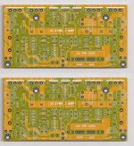
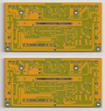
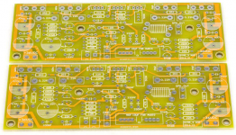
After doing a few more searches and comparisons I wonder if my boards and the jims_audio boards for the Symasym5-3 were done by the same PCB designer? (Or perhaps one copied from the other?)
The difference appears to be the removal of the fuses and an area/cost shrink.
Below:
The difference appears to be the removal of the fuses and an area/cost shrink.
Below:
- jims_audio (front)
- jims_audio (back)
- mine (front)
Attachments

Last edited:
The Symasym5 did not have two pairs of output devices... so this is probably not the same amp. Here is the official website SymAsym5 - Project
edit: What a surprise. China has ripped it off, and it's all over Aliexpress with two output devices and an increased power supply. The symasym is not suitable for rail voltages over 35V - the 2N5401/2N5551 devices used in the VAS will run too hot
edit: What a surprise. China has ripped it off, and it's all over Aliexpress with two output devices and an increased power supply. The symasym is not suitable for rail voltages over 35V - the 2N5401/2N5551 devices used in the VAS will run too hot
Last edited:
Thank you that helps a lot. (I wish I had found that earlier with the Gerbers.)
Comparing with the schematic for the board I bought (in post #4302) I do not see any show stoppers. Here are the differences:
So next I will examine the PCB layout and make sure it matches the schematic and also try to spot any layout issues.
I will not be using high voltage since my speakers are four Ohm. The "donor" AVR chassis that will be recycled has a large extruded heatsink and a dual voltage secondary (SecH and SecL). I believe I will have +/-32V DC using the SecL.
Perhaps the double/parallel 2SC5200/2SA1943 are ok since their capacitance is quite a bit less (each) than the MJL3281A/MJL1302A pair.
Any advice/suggestions would be appreciated as I am new to this amplifier.
Comparing with the schematic for the board I bought (in post #4302) I do not see any show stoppers. Here are the differences:
- The eBay/AliExpress board adds 22 Ohm emitter resistors for the MPSA18 input pair.
- The outputs are doubled and the base resistors changed from 1.2 Ohm to 2.2 Ohm (two, one for each output). (But they are lower capacitance outputs.)
- On the output the 4.7 Ohm 47 nF Zobel network was changed to 10 Ohm 100 nF.
So next I will examine the PCB layout and make sure it matches the schematic and also try to spot any layout issues.
I will not be using high voltage since my speakers are four Ohm. The "donor" AVR chassis that will be recycled has a large extruded heatsink and a dual voltage secondary (SecH and SecL). I believe I will have +/-32V DC using the SecL.
Perhaps the double/parallel 2SC5200/2SA1943 are ok since their capacitance is quite a bit less (each) than the MJL3281A/MJL1302A pair.
Any advice/suggestions would be appreciated as I am new to this amplifier.
Hi jaycee,
Thanks, you are absolutely correct as usual. Thank you especially for the link.
Hi kozard,
Most modifications made to the highly evolved design here by other people are probably not tested. Base resistance is not something you really want, and the lower stock values are what I would stick with.
The original design was tested and evolved carefully. The PCB design is also critical, so if your pattern differs your performance may not be the same. The layout can affect distortion and stability a lot.
-Chris
Sure. I could install just one MJL3281A/MJL1302A pair and the original 1.2 Ohm base resistor. I "suspect" that two pairs of 2SC5200/2SA1943 with two 2.2 Ohm (1.1 Ohm parallel equivalent) will "add up" to a similar total RC as the one MJL3281A/MJL1302A pair and the original 1.2 Ohm base resistor.Most modifications made to the highly evolved design here by other people are probably not tested. Base resistance is not something you really want, and the lower stock values are what I would stick with.
However it would be better to be sure. Someone must have build this other version but then again it might not be tested.
If I go with the original component values (one MJL3281A/MJL1302A pair and the original 1.2 Ohm base resistor) does that work well with 4 Ohm speakers?
I suppose I could order new boards from JLCPCB... ...sigh. Or build these, measure with REW/E-MU 0404 USB and listen to them. The trouble with eBay and AliExpress PCB/kits is that they are very easy to find but often are "modified" and/or suspect.
I will likely wait 7-10 days to see if anyone recognized my PCB and can verify the performance/end result.
Attachments
The Symasym5 did not have two pairs of output devices... so this is probably not the same amp. Here is the official website SymAsym5 - Project
That link contains a broken link to "Pavel's Site" which is referenced in regards to fixing an oscillation problem with 5200/1943 outputs. Do you happen to know if Pavel's site still exists somewhere?
I had to reduce my compensation capacitor to 10 pF using MJW0281 and MJW0302. So, you might be fine, just look at a square wave driving a load, 2 1/2 to 3 V signal is all you need. Adjust the compensation capacitor to reduce ringing. Once you find the right value, get a polystyrene for the best sound quality.
So, you need an oscilloscope and function generator for this. An 8R or 10 R resistor at 10 watts should be fine, but I used proper non-inductive 250 watt dummy loads.
So, you need an oscilloscope and function generator for this. An 8R or 10 R resistor at 10 watts should be fine, but I used proper non-inductive 250 watt dummy loads.
Actually I have an easy solution. I had bought MJL3281A/MJL1302A for repairing my L20.5 but when I compared 0281/0302 versus 5200/1943 (measured with REW/E-MU 0404 USB and EBG UXP/300 load) I found the distortion lower with the 5200/1943. So I never tried the MJL3281A/MJL1302A. (Soldering and desoldering 8 outputs on the L20.5 layout just to try is a bit of a chore.)
So I used the 5200/1943 in the L20.5 and I can repurpose the MJL3281A/MJL1302A for this one and avoid any guessing.
Is the attached layout the right one to order? (That is what I found from jaycee's link in Explendid amplifier designed by Michael Bittner, our MikeB) I just noticed that the JLCPCB shipping price is much better than earlier in the year so I can easily order the right boards. (Now I just need someone to point me to reliable/approved KSA50 MkII and Accuphase Gerber files and I will be finished my Christmas shopping. Seriously, if anyone knows the right gerber files to order for those please let me know. I like the sound of the KSA50 kit I built but I know it is missing what appears to be two emitter followers and various component values are different in the input section.)
Attachments

Last edited:
I don't have a PCB to compare it with that I can reach. It looks pretty darned familiar though. If there are differences, they are small. Mine are still working fine.
-Chris
-Chris
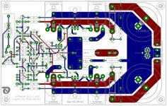
This is the original SYMASYM - website:
SymAsym5 - Project
I have attached a layout-design that I have done myself.
It works absolutely stable and fine.
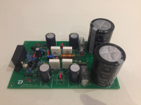
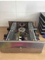
The other pictures show the SYMASYM with my layout as used in a home-cinema.
Regards - Rudi_Ratlos
SymAsym5 - Project
I have attached a layout-design that I have done myself.
It works absolutely stable and fine.
The other pictures show the SYMASYM with my layout as used in a home-cinema.
Regards - Rudi_Ratlos
Attachments
I built the headphone version from this post: Explendid amplifier designed by Michael Bittner, our MikeB
It sounds good as is. I get 3mv offset from power on to after 3 hours of operation.
Question: can I increase the input impedance of the amp from 22k (R14) to maybe 50k or even 100k? My tube dac has an output cap of only 1uf and I want better frequency response.
Thanks
It sounds good as is. I get 3mv offset from power on to after 3 hours of operation.
Question: can I increase the input impedance of the amp from 22k (R14) to maybe 50k or even 100k? My tube dac has an output cap of only 1uf and I want better frequency response.
Thanks
Hi walangalam,
You may upset the DC conditions for DC offset. Expect the offset to increase if you do that.
Now, what is the realistic low frequency limit of your headphones for starters? You may be chasing something that doesn't matter one little bit. The other option would be to use a buffer between the tube output and amplifier input.
Another question. When you turn your DAC on, is the output shorted to common until the tube has warmed up and is stable? The signal amplitude can be extremely high as the tube settles. If the input of any amplifier is exposed to that it can cause damage over time, or right away depending on a number of factors. A low-ish input impedance can help limit that amplitude, but if you increase it damage may occur.
-Chris
Thanks for the response, I think I am comfortable with 10mv offset, so Ill try using 50k. if it exceed this I will increase the 1uf cap and stay with 22k.
I have an Audeze LCD-2, and Stereophile measured it flat to 10hz. With a 1uf cap, at 10hz its about 2db down. I would rather have the amp exceed the headphone performance.
Somewhere in this thread MikeB prefers a 10uf input cap rather than a 4.7uf, and thats a smaller difference in freq response.
I dont have the output of the tube dac grounded on power up, so you have a point there. However, the amp has a 10 second speaker delay, plus I always power up the amp last in the chain. Hopefully this will do.
Hi walangalam,
The LF frequency response is a non-issue, believe me. You can't hear down to 20 Hz. The issue isn't the input cap so much as the high output impedance your tube stage probably has.
The input signal may damage the input stage, or at the very least it isn't good for it. So please install a muting circuit on the output of your DAC like all well designed units have. Once you do actually notice problems with the amp, the damage has become severe. This is a possibility, why take the chance?
The damage mechanism is reverse E-B breakdown of one of the pairs. Tube output stages have a habit of generating voltages in excess of the amount required for reverse breakdown.
No, the output delay and turn on - off sequence does not hep anything but your speakers.
-Chris

- Home
- Amplifiers
- Solid State
- Explendid amplifier designed by Michael Bittner, our MikeB