Hi Beycoast,
Sorry, not from personal experience.
Try searching this thread using your transistor numbers to see if anyone has used them. You will probably find the last pair you listed were used by someone.
-Chris
Edit: Thanks Allen
Sorry, not from personal experience.
Try searching this thread using your transistor numbers to see if anyone has used them. You will probably find the last pair you listed were used by someone.
-Chris
Edit: Thanks Allen
Hi Beycoast,
Sorry, not from personal experience.
Try searching this thread using your transistor numbers to see if anyone has used them. You will probably find the last pair you listed were used by someone.
-Chris
Edit: Thanks Allen
Thanks Chris
I couldn't find exactly what I was looking for, but I created a prototype by trial and error method. The result is fine
I've been looking at a lot of amplifier circuits lately and noticed the following; the symasym amplifier touted here, apparently designed around 2005, is *very* similar to the power amplifier design of the Arcam Diva AVR100 receiver which was released circa 2001. What do you think? Obviously I can't post that schematic here as it's the property of Arcam, but it's out there if you care to look.
I build the amplifier and ran into a problem that I can't solve. First of all, I am a beginner in audio engineering. I can solder and play a little with the multimeter thats all.
Now the amplifier is not working properly. A symptom is that I have to set the volume of the source very high so that something comes at all and what comes next is very noisy and scratchy.
So now it is also the case that I cannot measure the bias, for example, as long as no source is connected, the voltage remains at the emitter legs of the transistors at 0mV or a little above but then quickly becomes apparent 0mV.
Has anyone a idea where to start to troubleshoot?
An externally hosted image should be here but it was not working when we last tested it.

If it helps, I have tested different frequencies on the advice of a friend. The lower frequencies worked (not good but worked) above 5000khz it stops to work and the result is as described above.
MJL3281 availibility
Hi, I am actually purchasing parts for my SymAsym and found that the output transistors are unavailable, probably till end of the year (at least from official distributors and I don´t want to take the risk of fake devices) Therefore I decided to go on with the Toshiba 2SC5200.
I read in the forum (and on Mike´s page as well) that these are more critical in regard to oscillating. I also read that pavel posted some changes to make it stable. Unfortunately I am not able to find the schemes. Mike writes on his page that at least the feedback compensation cap must be changed to 10pf - but are there other changes, too?
Thanks for your replies!!
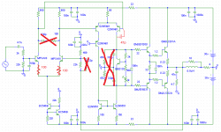
In the schematic on the first post, it only uses lag compensation in the input stage. I don’t think it is enough to make the whole thing stable.
Here is my suggestion.
1. Remove the compensation in the input stage.
2. Degenerate the input transistors with 100 Ohm resistor, so you will get a well defined gm.
3. Put a 47p Miller cap on the VAS. (Right side of VAS only)
Here is my suggestion.
1. Remove the compensation in the input stage.
2. Degenerate the input transistors with 100 Ohm resistor, so you will get a well defined gm.
3. Put a 47p Miller cap on the VAS. (Right side of VAS only)
Last edited:
MJL3281 availibility
Many thanks for the quick response!
Just to make sure I understood right:
Remove compensation in the input stage: Is the 22p cap in the feedback loop meant?
Degenerate input transistors: Does that mean two 100 Ohm resistors directly to the emitters of the MPSA 18´s? Is this the same as Michael recommends when reducing the gain?
47p Miller cap - didn´t understand this - what does "VAS" mean (sorry for asking stupid questions)
VAS: voltage amplification stage.
Please see my changes below.
Attachments
Last edited:
Hi jxdking,
Disagree with you completely!
The original and variants of this amplifier worked just fine. Before hacking a working design, why not build it as designed? Just because you have your own ideas doesn't mean you can remove compensation at will and change things expecting them to work.
Here's an important question for you. Have you built one of these? Have you actually built the design you recommended? How many? If you are just driving a simulator, I don't think you are qualified to make suggestions such as these. If you have, please post the PCB design as this also impacts the compensation.
-Chris
Here's an important question for you. Have you built one of these? Have you actually built the design you recommended? How many? If you are just driving a simulator, I don't think you are qualified to make suggestions such as these. If you have, please post the PCB design as this also impacts the compensation.
I will not build one unless it performs well in the simulation.
It is fine to disagree. Miller compensation is the one I am familiar with. That is how I tackle the stability issue. I know not everyone likes the taste of Miller compensation.
One thing it is good to point out. If the original design works fine, don't change it.
I want to add some note to the method that I mentioned in Explendid amplifier designed by Michael Bittner, our MikeB
I can tell the original author wants to avoid Miller compensation. The original design has higher slew rate and bandwidth comparing the changes I proposed. If you don't have issue, don't fix it.
Thank you very much, your support is very much appriciated! Did you build this modified version? How does it sound in comparison to the original MJL´s?
Best regards,
Johannes
Best regards,
Johannes
Hi jxdking,
Well, I feel it is irresponsible to recommend making changes to a working design to someone who actually is investing time and effort when you have not even attempted to build one.
It is likely that stability issues will occur with your changes as the actual design was fine tuned using a working prototype. It was tested by many actual builders and experienced technicians, myself included in that group.
As a general rule, I don't think it is proper or reasonable to offer modifications to a working design based solely on a simulator run. This is especially true when your advice is to a person who is actively building one.
Best, Chris
the comp on the differential pair works better there as it preserves the slew rate. keeping that comp along with a 5pf miller cap instead of the 47pf would halt any oscillations brought on by faster or newer transistors. keep the 100 ohm emitter degeneration resistors as well.
Hi Johannes,
A higher slew rate does not always equate to improved performance. Often, if there is any improvement, it is inaudible as it will be a small change.
Way back when I built mine (still working well), I used MJW0281 and MJW0302 outputs. I only needed 10 mA of bias current approximately. Back then I posted my findings.
What does make a massive difference is how closely matched the input pair is. Without using a jig I designed (and gave the design to the community), the best you can do is maintain the transistors at room temperature and test them using tweezers. Don't even breathe on them as transistors are very temperature sensitive. Once you have a pair, mount them together in heat shrink tubing. A touch of thermal compound between hem doesn't hurt either.
The jig that was designed maintains the same temperature between the pair under test and would be of use to a technician that does fine work, or a hobbyist that will put in the effort and builds more than one stereo amplifier. It is too expensive to build as a one-off. The details are in one of the Adcom GFA-565 threads near the end. Two different PCBs were designed for it in addition to mine.
-Chris
Hi anatech,
thanks for your interesting thoughts! I also built this amp years ago and I am still impressed by the sonic quality of the design.
As you recommended, I also did a very tight transistor matching and made the same experiences with e.g ambient temperature during matching procedure...
Now I need some more channels because I want to run my Beyma 15 inch coaxes actively. Of course I want to prevent a degraded design in comparison to my old ones.
Do you think it´s worth waiting for the MJL´s? (MJW´s would be a good alternative but seem now to be obsolete / unavailable, too.)
Do you know anybody who actually built the amp with Toshiba´s?
As I found out, Fairchild / Onsemi is also offering the 2SC5200, with lower current gain in comparison to the Toshibas - could this have a positive effect on stability?
The photo on Michael Bittner´s page shows a build with Toshibas - obviously he changed only one cap in the overall feedback loop from 22 to 10pF? (the emitter resistors for the input stage he recommended only when reducing the amp´s gain)
Regards,
Johannes
loop gain
The simulation is based on the schematic in the first post. Hope I did not screw up this. 😀
Here is my observation.
1. It is stable. Clean square wave at 10KHz. Credits to the author.
2. The ULGF (unit loop gain frequency) is high up at 4MHz, comparing average amplifier that only gets 500k - 1M ULGF. That means it probably won't work on bread board. You need good PCB layout and component selection to make it stable at 4MHz.
3. You get near 60dB feedback at 10KHz, which guarantees low THD. Under 100mA bias in my simulation, I get 0.007% THD @10KHz +-20Vpk-pk.
Last edited:
Hi Johannes,
Try the MJL2119x transistors. Performance might even improve due to better current vs collector current characteristics. I have found these parts to be very good.
Yes, they discontinued the MJW parts long ago, and that was really too bad. They were a really great part! That's why I used them. I would use them today both for service and new designs if they were still available.
Hi jxdking,
You shouldn't need anywhere near that high a bias current. Even 30 mA is very high. My actual amplifier distortion was lowest somewhere between 5 and 10 mA. I can't remember now. Distortion increased above that level. Real world testing into the proper Dale 250 watt, 8R, 1% non-inductive loads.
-Chris
My actual amplifier distortion was lowest somewhere between 5 and 10 mA. I can't remember now. Distortion increased above that level. Real world testing into the proper Dale 250 watt, 8R, 1% non-inductive loads.
What is frequency of distortion that you measured?
- Home
- Amplifiers
- Solid State
- Explendid amplifier designed by Michael Bittner, our MikeB