The problem a second project are when i adjust biasing at 2.0 mv in 5 second biasing to be 630 mv
What should i do?
What should i do?
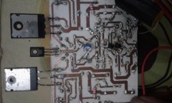
Your two pics are just over 2500 pixels wide.
Your pcb is only 808 pixels wide.
You can compress your pics down to around 1000 to 1500 pixels wide (or tall) and still see lots of detail.
Compare the detail in the 808.
Your pcb is only 808 pixels wide.
You can compress your pics down to around 1000 to 1500 pixels wide (or tall) and still see lots of detail.
Compare the detail in the 808.
I don't understand what you are doing, nor what you are measuring?The problem a second project are when i adjust biasing at 2.0 mv in 5 second biasing to be 630 mv
What should i do?
I mean the first build symasym is white pcb the result when i measuring the bias at both of emiter final is 0 mv i adjust with vr 1k still 0 mv, and than i build 1 again with brown pcb and i measuring bias , i adjust at 2.3mv , 5 second than be 630 mv reads at my dmm, sory if my english not good enough
If the bias increases very quickly then it could be thermal runaway. Are you performing this test with all three transistors fixed to a proper heatsink (all correctly insulated of course) ?
I note that in the picture the Sanken transistors only had screw in one side of each one so they may not be flat against heat sink.
Also it looks like the Bias transistor BD139, is half sitting on the Sanken transitors insulator, so I guess it's not properly in contact with heat sink.
Even so 5 seconds is a very fast bias rise, if it's stable after reaching 630mV perhaps this is due to capacitor charging? Cany hte bias be reduced from 630mV ?
The problem a second project are when i adjust biasing at 2.0 mv in 5 second biasing to be 630 mv
What should i do?
Most likely, as soon as bias reached certain level - the amp starts oscillating.
Do you have an oscilloscope connected to the output?
Most likely, as soon as bias reached certain level - the amp starts oscillating.
Do you have an oscilloscope connected to the output?
Interesting point, but not every one has a scope.
A useful alternative might be to make an HF probe for DMM.
I'm thinking of somethng along the lines of connect a diode (1n4148), in serise with small capacitor (220pf) to block DC and LF signal, and a resistor as load (6800 ? ). connect other end of resistor to ground, and diode to the output. Measure across the resistor, and perhaps a second capacitor across the resistor (0.01uF?) to smooth the resulting signal.
I'm travelling so can't confirm exactly how well these values will work.
but should show if anything significant is happening at 200Khz or higher.
I note that in the picture the Sanken transistors only had screw in one side of each one so they may not be flat against heat sink.
Also it looks like the Bias transistor BD139, is half sitting on the Sanken transitors insulator, so I guess it's not properly in contact with heat sink.
Even so 5 seconds is a very fast bias rise, if it's stable after reaching 630mV perhaps this is due to capacitor charging? Cany hte bias be reduced from 630mV ?
Stable maybe, i try in about ten second and heatsink very hot, iit can't be reduce, i must off and on again biasing be 2,3 mv and 5 second rise againt
Most likely, as soon as bias reached certain level - the amp starts oscillating.
Do you have an oscilloscope connected to the output?
No i didn't have, just dmm digital and other
I measure with no speaker and input,
I was checking all resistor and i find no one of their value was right, like 150 ohm read 144 ohm, is that normally?,
I note that in the picture the Sanken transistors only had screw in one side of each one so they may not be flat against heat sink.
Also it looks like the Bias transistor BD139, is half sitting on the Sanken transitors insulator, so I guess it's not properly in contact with heat sink.
Even so 5 seconds is a very fast bias rise, if it's stable after reaching 630mV perhaps this is due to capacitor charging? Cany hte bias be reduced from 630mV ?
Stable maybe, i try in about ten second and heatsink very hot, iit can't be reduce, i must off and on again biasing be 2,3 mv and 5 second rise againt
It is a new one that i had build
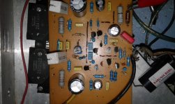
Is that big Karunia Baru thingie the capacitor in your nfb decoupling arm to earth.
If so remember this element connects to the inverting input of the amplifier and capacitors are wound components - you don't want to be picking up signals radiated by your output stage. The output stage resistors also have inductance as these are wire-wound. Don't invite this sort of trouble.
Make a second zobel using 10R 1/4W resistor in series with a 100nf/250v capacitor,No i didn't have, just dmm digital and other
I measure with no speaker and input,
Connect this at amplifier output.
If you see a smoking resistor the amplifier oscillate.
Turn off immediately!
Has anyone ever done a simulation of this circuit to find out how stable it is? If there is I would like to see it.
From the rough one I have done it has overshoots on 10 kHz square wave with not a lot of capacitance in parallel with 8R - even at low signal input levels.
From the rough one I have done it has overshoots on 10 kHz square wave with not a lot of capacitance in parallel with 8R - even at low signal input levels.
I'm sure, it oscillates as soon as the bias exceeds certain level, due to particular build specifics. There may be other issues, but the simple ones I'd like to mention:
- rather "dirty" bottom side of the board - you may want to clean it with white spirit and carefully dry before powering it on again;
- rather inaccurate mounting of the drivers, outputs and temperature sensing transistor on the heatsink - it would make sense to mount them a bit wider, using all the screws and insulation pads of the right size - proper thermal contact is important.
- Output transistors combination is sub-optimal - complementary pairs are:
2SC2922 / 2SA1216
2SC3858 / 2SA1494
- Home
- Amplifiers
- Solid State
- Explendid amplifier designed by Michael Bittner, our MikeB