Thanks alot.
Well, I bought most of my resistors and small capacitors and also 3 of the 5 electrolytics at reichelt, but all semiconductors (like the 2sc and the MJ, MJL and 2N types) were bought together with some other stuff at segor-electronics in berlin.
I beleive that the reichelt mjl are not geniue onsemi devices. In former times I often got these inchange semiconductors from reichelt.
Segor is great, very fast and friendly, good program, high quality parts, and not too expensive. Still one mjl costs about 6 euros. But its worth ervery single cent in your design!
I just had a bit of listenig with my new symasym. The sound is incredible with my old "cestion ditton" speakers. Very clear and "strong", while being natrual.
As you can see on the pictures, I've installed a bypass switch for the volume-pot. In future this AMP will be running in a biamping configuration. If you leave the pot out, the sound is even better!
Greets
Black
Hi BlacK_Chicken,
-Chris
My guess is that there is no buffer after the volume control. BJT inputs sometimes need a low impedance source to drive it. Nakamichi called it HTA (a breakthrough!), Marantz used it in the model 500 amp. The 500 was released in 1968, those guys were pretty sharp I'd say. 😉If you leave the pot out, the sound is even better!
-Chris
Hello anatech,
Yes, theres no buffer after my volume-pot.
Just a 20k log. alpha potentiometer and into the amps.
I have to build my Quasi NMOS power AMP for the lower frequencies and an active 2way crossover to comple my active system. Then I throw that pot out (by switch).
Many thanks and greetings
Black
Yes, theres no buffer after my volume-pot.
Just a 20k log. alpha potentiometer and into the amps.
I have to build my Quasi NMOS power AMP for the lower frequencies and an active 2way crossover to comple my active system. Then I throw that pot out (by switch).
Many thanks and greetings
Black
Nordmende
Hi Black,you made a very good looking Highend Nordmende amplifier.
The wiring is SOTA and has cost you a lot of time i think.
Compliments.
Loek
Hi Black,you made a very good looking Highend Nordmende amplifier.
The wiring is SOTA and has cost you a lot of time i think.
Compliments.
Loek
Thank you very much, yes the wirering took some hours. But the mounting of the Transistors on the heatsink (I had to bend all Pins, because of the 3mm distance on the board) took even longer. 🙂
Since this Morning I am listening constantly, really good sound.
Steve Strauss, Sara K. and Chris Jones sound fabulous!
Greetings
Since this Morning I am listening constantly, really good sound.
Steve Strauss, Sara K. and Chris Jones sound fabulous!
Greetings
A new symasym like amplifier is ready to see the light
You are invited to make your comments, criticize topology and PCB layout, at this address
Thank you,
Mihai
http://www.diyaudio.com/forums/showthread.php?postid=1135809#post1135809
You are invited to make your comments, criticize topology and PCB layout, at this address
Thank you,
Mihai
http://www.diyaudio.com/forums/showthread.php?postid=1135809#post1135809
-_nando-_ said:I dindn't adjust the bias of my amps...
I forgot to do it, and I could remember when it was playing in my house, COLD. It don't get more than warm, no pop noise when I turn it on, no Hum or hiss at all.
So, why should I open the case and adjust the bias? 😕
I'm curios, and didn't have an answer yet

edit: Sorry ! Mike already answered and I didn't see ! 😀
Hi Mihai,
Nice job. I am looking forward to hear your impressions and possibly some real world measurements.
-Chris
Nice job. I am looking forward to hear your impressions and possibly some real world measurements.
-Chris
Unfortunately, I don't have any possibility to make real time measurements, other than stability and proper working.
I will trust my ear and if I'm very lucky, maybe one of my favorite forum mate will build the amp and make some THD measurements.
I will trust my ear and if I'm very lucky, maybe one of my favorite forum mate will build the amp and make some THD measurements.
Hi Mihai,
-Chris
That will do for a start. How high are your supplies running?Unfortunately, I don't have any possibility to make real time measurements, other than stability and proper working.
If I can get back to making PCB's, I may give them a try as well.I will trust my ear and if I'm very lucky, maybe one of my favorite forum mate will build the amp and make some THD measurements.
-Chris
Hi Mihai,
At 45VDC, you are starting to get into a higher power area (that others have been asking for). Also where heat becomes more of a problem. I am interested in how warm your drivers will get.
-Chris
At 45VDC, you are starting to get into a higher power area (that others have been asking for). Also where heat becomes more of a problem. I am interested in how warm your drivers will get.
-Chris
The current in drivers (CFP power devices) will swing between 70-130mA. At 45V rails, maximum dissipated power into drivers will not exceed 6W/device.
The power disipated in CFP driver will not be more than 250mW.
More than safe powers related to SOA of those devices (2n5401/5551 and mje15034/15035)
The power disipated in CFP driver will not be more than 250mW.
More than safe powers related to SOA of those devices (2n5401/5551 and mje15034/15035)
Hi Mihai,
-Chris
That's what I was worried about. You have planned them to be mounted to the PCB, but you may need more heatsinking for them.At 45V rails, maximum dissipated power into drivers will not exceed 6W/device.
-Chris
Hi Mihai,
That works.Drivers are monted on heatsink under PCB, on the solder side like smd devices.
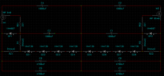
FET regulator
Hi everybody,
I've finished to work on a regulation stage which is good for Symasym. It is composed by two FETs, IRF 540 and IRF 9540. It is strongly adapted from a Pass-like design as you 'll see. I hope this regulator will be good for you.
Greets,
Max.
Hi everybody,
I've finished to work on a regulation stage which is good for Symasym. It is composed by two FETs, IRF 540 and IRF 9540. It is strongly adapted from a Pass-like design as you 'll see. I hope this regulator will be good for you.
Greets,
Max.
Attachments
Hi all,
is there a homepage with all new developments concerning symasym.
Do you know someone who offers a DIY kit for symasym?
Regards
tolu
is there a homepage with all new developments concerning symasym.
Do you know someone who offers a DIY kit for symasym?
Regards
tolu
Hi Tolu, for the case you don't know it:
http://www.analog-forum.de/wbboard/thread.php?threadid=25151
http://www.symasym.holgerbarske.com/doku.php
This should result in a group buy for boards and more...
Mike
http://www.analog-forum.de/wbboard/thread.php?threadid=25151
http://www.symasym.holgerbarske.com/doku.php
This should result in a group buy for boards and more...
Mike
- Home
- Amplifiers
- Solid State
- Explendid amplifier designed by Michael Bittner, our MikeB