Hi Al,
That's looking good. I haven't built the supply yet as I'm using a test supply at the moment.
-Chris
That's looking good. I haven't built the supply yet as I'm using a test supply at the moment.
-Chris
Mirrored Symasym
Hello Mike
I can' t believe there is another mirrored Symasym! And I thought
mine was the only one, the unique!
I feel a little...oh, deceptioned, to say the least...
But life goes on, it works, and it works good, that;s what matters!
Hello Mike
I can' t believe there is another mirrored Symasym! And I thought
mine was the only one, the unique!
I feel a little...oh, deceptioned, to say the least...
But life goes on, it works, and it works good, that;s what matters!

Re: Mirrored Symasym
Don't be deceptioned. Yours always will be unique, a pioneer ... 😉
jmateus said:... I thought mine was the only one, the unique!
I feel a little...oh, deceptioned, to say the least...
[/B]
Don't be deceptioned. Yours always will be unique, a pioneer ... 😉
symasym grounding
Apologies if this was covered hundreds of posts ago...
Would I be right in thinking that both ends of R2 are grounded to the star, along with Vgnd and Ignd and input and output grounds?
thanks!
Apologies if this was covered hundreds of posts ago...
Would I be right in thinking that both ends of R2 are grounded to the star, along with Vgnd and Ignd and input and output grounds?
thanks!
Principally, the idea was that Ignd is only connected to the ground of the input rca jacket. This of course works only if groundpotentials of connected devices do not really differ.
Even if ignd is also connected to the groundstar, it's slightly seperated from the gnd on the amp-pcb through r2.
Sorry, my grounding skills are not the best...
BTW, nothing to sorry, this was not really covered in the last 2787 postings.
Mike
Even if ignd is also connected to the groundstar, it's slightly seperated from the gnd on the amp-pcb through r2.
Sorry, my grounding skills are not the best...
BTW, nothing to sorry, this was not really covered in the last 2787 postings.
Mike
Hey Mike!
An idea.
A thread for "Troubleshooting your Symasym" might help. Or something like "Smyasym Assembly"
-Chris
An idea.
A thread for "Troubleshooting your Symasym" might help. Or something like "Smyasym Assembly"
-Chris

anatech said:Hey Mike!
An idea.
A thread for "Troubleshooting your Symasym" might help. Or something like "Smyasym Assembly"
-Chris
Chris - what a bright idea!
Poor Mike 😉
PMA said:
Chris - what a bright idea!
Poor Mike 😉
Doesn't have to be Mike - seems a lot of folk have built this amplifier.
The Krell clone thread has its own wiki. Maybe we could do something for the symasym?
I say "we", I haven't built it yet...though I have the transformer and caps ready 🙂
Was also considering using a double-sided board (for a ground plane). Mike suggests a heavy wire linking the grounds of the decoupling caps; a big copper plane would be even better.
I really should redo the pcb layout, the best would be a groundstar where the heavy wire linking is now located. I learned a lot about grounding since i made that layout. Doublesided would make many things easier...
The latest measurings showed me that symasym would be capable of ~0.001%, and looses a lot of performance only because of grounding/wiring/layout.
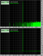
Pavel, i analyzed your wave file (the 1025.5khz thing), you should have told me that i forgot the dithering... That gave all these nice spectral lines... What a difference ! Attached is fft of same wave without and with dithering.
BTW, i have another idea why the jfets sound better, is it possible that they increase psrr at an audible level ? Variations from the ccs will modulate the base currents for q1/q2, having an impedance unbalance at ac to the bases (only dc is balanced), these variations are not eliminated. This effect would not exist with jfets...
Mike
The latest measurings showed me that symasym would be capable of ~0.001%, and looses a lot of performance only because of grounding/wiring/layout.
Pavel, i analyzed your wave file (the 1025.5khz thing), you should have told me that i forgot the dithering...
That gave all these nice spectral lines... What a difference ! Attached is fft of same wave without and with dithering.BTW, i have another idea why the jfets sound better, is it possible that they increase psrr at an audible level ? Variations from the ccs will modulate the base currents for q1/q2, having an impedance unbalance at ac to the bases (only dc is balanced), these variations are not eliminated. This effect would not exist with jfets...
Mike
Attachments
Any chance of giving a pair of BS107 or BS170 or 2N7000 a go as the input pair? They are only about 10c here, so shouldn't break the bank...
Regarding the PCB, yu said ' the best would be a groundstar where the heavy wire linking is now located'... IIRC I actually said exactly that in one of my posts 🙂
Regarding the PCB, yu said ' the best would be a groundstar where the heavy wire linking is now located'... IIRC I actually said exactly that in one of my posts 🙂
But if the jfets sound really good, why change back to bjt's? In this case the MPSA18 were the ones...
Hi John, the transistors mentioned by ilimzn are mosfets, not bjts.
And there is one thing i can't accept, not knowing/understanding why a certain change sounds better... 😕
Mike
And there is one thing i can't accept, not knowing/understanding why a certain change sounds better... 😕
Mike
MikeB said:I really should redo the pcb layout...Doublesided would make many things easier...
I'm sitting here playing with it as we speak, thirded for double sided.
*pinkmouse said:
I'm sitting here playing with it as we speak, thirded for double sided.
so am I, and so do I...are you using Protel?
- Home
- Amplifiers
- Solid State
- Explendid amplifier designed by Michael Bittner, our MikeB