Chris, stability is obviously not the problem... The 10khz looks perfect...
The thd looks too big, just like there is crossoverdistortion ?
I had this treble problem also with the MJL21196/5, higher bias (>100ma) solved it.
What is the total current consumption of the amp ? It should be ~100ma.
Mike
The thd looks too big, just like there is crossoverdistortion ?
I had this treble problem also with the MJL21196/5, higher bias (>100ma) solved it.
What is the total current consumption of the amp ? It should be ~100ma.
Mike
Hi Mike,
-Chris
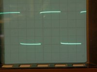
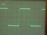
Possibly even a little rolled off actually. Could be the input network doing that. Not that I'll complain because the 10 KHz square wave looks great. You can see a little droop in the 1 KHz square wave from the coupling caps.stability is obviously not the problem... The 10khz looks perfect...
I was going to hunt for the "happy" bias point. It may be higher or lower. These effects may be from the drivers rather than the outputs. The sound quality will be capacitor related, if you look at the board picture. I can't easily measure the current draw at this moment except to say that the actual bias current in the outputs is close to 60 mA.I had this treble problem also with the MJL21196/5, higher bias (>100ma) solved it.
-Chris
I also use ~60ma with the ML0281/0321, and they sound absolutely clean... 😕
Is the issue easily audible, or very subtile ?
Mike
Is the issue easily audible, or very subtile ?
Mike
Hi Mike,
The bias point for lowest distortion was found to be about 22 mA. I was looking at the residuals at 10 KHz at 1.5 V rms into both 8 ohms and 4 ohms. At 22 mA the crossover distortion is completely gone, past that point a bit really. Above 22 mA there is increasing supply noise and hash, but no oscillation.
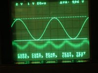
So here is what things look like now Mike. The measured distortion is higher, but the level is now at 1.75 V for this shot and measurement. I am seeing 0.028% right now. Not bad by the way.0.024% THD at 1 KHz with a similar residual. I am fairly certain that this is front end stuff.
-Chris
The bias point for lowest distortion was found to be about 22 mA. I was looking at the residuals at 10 KHz at 1.5 V rms into both 8 ohms and 4 ohms. At 22 mA the crossover distortion is completely gone, past that point a bit really. Above 22 mA there is increasing supply noise and hash, but no oscillation.
So here is what things look like now Mike. The measured distortion is higher, but the level is now at 1.75 V for this shot and measurement. I am seeing 0.028% right now. Not bad by the way.0.024% THD at 1 KHz with a similar residual. I am fairly certain that this is front end stuff.
-Chris
Attachments
Hi Mike,
Audibly, more subtle. I'm sure most people would not hear this at all. The point I'm after is to identify things that make amps sound a certain way, and to improve upon this one. It is to be an education for me.
Understandably, that would make it more complicated. You achieved an amplifier that surpassed your original performance already I think. This may take the design well past the point in complexity (I hope not!).
-Chris
Ah, the issue i had with the 21195 was not subtile, in this case i guess it is caused by the ceramics.
That's a wonderful tool you have ! Now you see that the distortion left is nearly only 2nd harmonics, no crossover left. Are you really using 0.22ohm emitter resistors ? If yes, this 24mv rule is... wrong. Damn.
This could mean that each device has its own optimal bias ?
Have you already checked audible difference ?
Mike
Hi Mike,
If you look closely at the resistors I used for emitter resistors, you will see they are not standard. They are a low inductance type. Still wire wound. They measure 0.20 ohms.
So far I can not hear any difference. My feeling is that these differences are swamped out by other factors. Ceramics for sure, and you won't see this with the sine wave tests.
Once I have the cap issues sorted out, I'll be having a look at the voltage amp stage. A cascode will be needed for the new parts, but I'll check with the original transistors to get an idea on circuit influence.
-Chris
Ah, another idea, could you connect ground to the VGND pin instead to the wire bridge ? Maybe the increased THD is from that ?
BTW, is the THD value maybe THD+N ?
Mike
BTW, is the THD value maybe THD+N ?
Mike
anatech said:Hi Mike,
The bias point for lowest distortion was found to be about 22 mA. I was looking at the residuals at 10 KHz at 1.5 V rms into both 8 ohms and 4 ohms. At 22 mA the crossover distortion is completely gone, past that point a bit really. Above 22 mA there is increasing supply noise and hash, but no oscillation.
So here is what things look like now Mike. The measured distortion is higher, but the level is now at 1.75 V for this shot and measurement. I am seeing 0.028% right now. Not bad by the way.0.024% THD at 1 KHz with a similar residual. I am fairly certain that this is front end stuff.
-Chris
Chris, what was the low pass filter setting on your analyzer when you did this shot?
Jan Didden
anatech said:The measured distortion is higher, but the level is now at 1.75 V for this shot and measurement. I am seeing 0.028% right now.
-Chris
This is a poor result.
Hi Guys,
The Leader does not have a low pass filter. All the HF stuff comes riding on through. But that's okay because it does not dominate the residual. The 400 Hz high pass filter was switched out, I forgot to put it back in when I was looking for noise.
My oscillator (Leader Lag-120B) isn't the best. I should put my (fet controlled) wien bridge oscillator back together some day. My measured THD from that is 0.032%. That, is not good.
Hey Al,
Sorry, I missed your post. I matched my transistors as well. 😉 I am officially disabled at the moment. What's your excuse? 😉
😉
-Chris
The Leader does not have a low pass filter. All the HF stuff comes riding on through. But that's okay because it does not dominate the residual. The 400 Hz high pass filter was switched out, I forgot to put it back in when I was looking for noise.
My oscillator (Leader Lag-120B) isn't the best. I should put my (fet controlled) wien bridge oscillator back together some day. My measured THD from that is 0.032%. That, is not good.
Mike, I was going to experiment with this connection. It is only used to ground the heatsink. I will play with that further.Ah, another idea, could you connect ground to the VGND pin instead to the wire bridge ? Maybe the increased THD is from that ?
Hey Al,
Sorry, I missed your post. I matched my transistors as well. 😉 I am officially disabled at the moment. What's your excuse?
😉 -Chris
Looking for a new job, got made redundant, so I'm saving the pennies at the moment! 🙂
Actually, I probably have 90% of the bits I need, just missing a traffo and a few caps, it's time more than anything that's in short supply.
Actually, I probably have 90% of the bits I need, just missing a traffo and a few caps, it's time more than anything that's in short supply.
Chris, why not using your new soundcard as signalgenerator ? (for sinus waves only)
If you playback the sinewave at ~-3db you should get a signal with ~0.001% thd.
Hey Al, you have etched the PCBs, matched the transistors, maybe not drilled the PCBs yet ?
Pavel, not "horrible" ? 😉
Mike
If you playback the sinewave at ~-3db you should get a signal with ~0.001% thd.
Hey Al, you have etched the PCBs, matched the transistors, maybe not drilled the PCBs yet ?
Pavel, not "horrible" ? 😉
Mike
Nope, PCBs are drilled. I really am running out of excuses.
Ah-ha! I don't have an enclosure to put it in? 😀
Ah-ha! I don't have an enclosure to put it in? 😀
anatech said:Hi Guys,
The Leader does not have a low pass filter. All the HF stuff comes riding on through. But that's okay because it does not dominate the residual. The 400 Hz high pass filter was switched out, I forgot to put it back in when I was looking for noise.[snip]-Chris
Hi Chris,
Reason I ask is, it looks just like 10kHz cross-over filtered through a 22kHz (which is standard) low pass of the analyzer. Has caught me more than once on the AP.
Might just be worthwhile to look up the freq response of the analyzer just to make sure what it is you see.
Jan Didden
pinkmouse said:Nope, PCBs are drilled. I really am running out of excuses.
Ah-ha! I don't have an enclosure to put it in? 😀
Bad excuse... 😀
But not having the traffo at the moment and beeing a bit out of money is a good excuse.
Jan, good point, but the crossover distortion was visible at other bias levels, and the last measurement was at 1khz i believe.
Mike
Hi Al,
I just found out that WSIB cut my benefits of as of Aug, 31. Nice eh? No warning.
Hi Mike,
Before I can use my sound card, I need to switch it to another computer, before that I have to solve some WinXP compatibility problems (other box is '98). I also need to build and calibrate an input attenuator for it.
-Chris
I am very sorry to hear that. Best of luck mate!Looking for a new job, got made redundant, so I'm saving the pennies at the moment!
I just found out that WSIB cut my benefits of as of Aug, 31. Nice eh? No warning.
Ah-ha! Neither do I! Haven't even thought about it yet. Don't have a transformer either. These things will come. 😉 Good one though. The time thing I'll believe. I have the same problem.Ah-ha! I don't have an enclosure to put it in?
Hi Mike,
Before I can use my sound card, I need to switch it to another computer, before that I have to solve some WinXP compatibility problems (other box is '98). I also need to build and calibrate an input attenuator for it.
-Chris
- Home
- Amplifiers
- Solid State
- Explendid amplifier designed by Michael Bittner, our MikeB