A very good news from you Sheldon.
One of my Symassym 4 units are using 220uF as input capacitor...because it is operating only to sub bass.... a passive input filter is beeing used.
When ready.... go turning volume all the way up...will be very surprised with the low distortion and power provided.
Good to know i am free of the "Charlotte" name..... good to perceive you are happy.
Find some amplifier and compare..... excepting GEM and Aksa, i am afraid you will be deceptive with the unit you choice to compare.....Symassym will produce impressive sound.
Thank you, because of your informations.
And have fun with it....you will feel very good with it.
regards,
Carlos
Hi Sheldon !
Nice to have you back !
And thanks for the compliments, i am anxious about your final evaluation...
And nice to have you back Carlos ! Computer fine again ?
Mike
Nice to have you back !
And thanks for the compliments, i am anxious about your final evaluation...
And nice to have you back Carlos ! Computer fine again ?
Mike
I think so!.... touching bios chip i had problems...so...i solder it again.
I never had inform of such a problem....but now it is working fine.
Good to have Sheldon again....i think he already told that sound fine.... Sheldon do not talk too much...he is more to think deeply than to talk Michael.
I think we will have more two paragraphs...and will delay some time...as this one do not like to talk without be absolutely sure.
This is good....i apreciate his care.
He told me the more important...he kicked "Michaela"...this is very good!
Also 14 guys that constructed Graham amplifier told the same...that my name will continue to be Charles.
He he.... relief.
regards,
Carlos
Hi all !
I updated my measurements, i was able to get rid of most artefacts,
now looks much better than my previous result !
I still have some problems left, somehow halfwaves from the supplywires
induce signals somewhere... This creates the "big" even harmonics.
The hum seems to come from the amp not beeing in a shielded case,
most of it is already present before amp is turned on...
http://www.lf-pro.net/mbittner/rmaa/Symasym4_cd_3.htm
I have not changed the amplifier itself, only wiring and groundconnections.
It looks like that without the induced signals the thd is somewhere at 0.001%.
It's really horrible that wrong wiring can change thd about factor 100 !!!
I got everything from 0.12% to 0.0012%...
Mike
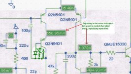
Michael, yesterday i was observing small differences in current related up and down
differential voltage amplifier related its mirror.
The rigth one is conducting more....so a preference for input or feedback will happen there.
I do not know if you will understand what i mean...but maybe, suggesting a diode in the Voltage divider auxiliary transistor...the one with base to ground.... a series diode there....before the base, with a resistor in parallell to adjust current in upper transistors..... well...matching them perfectly, without any room to milivolts fluctuations there.
If not understood...hehe.... i am not designer, nor a programmer....so, you may not understand me..... so.... tell me and i will send a MP3 audio to you.
regards,
Carlos
Hi Carlos !
Yes, i think i understood you !
Are the differences measured bigger than the currents shown here ?
http://www.diyaudio.com/forums/attachment.php?s=&postid=683534&stamp=1121552477
You mean the difference between the 2.466ma and the 2.442ma ?
This is hard to avoid and is caused by unbalanced load from the
unmatched mje15030/31.
About the diode, you can put it to the emitter of the voltagedivider-bjt,
that is much simpler !
The slight imbalance in the currentmirror can be killed by a cascode,
eliminating the 2nd harmonics, but who wants that ?
Mike
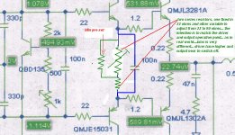
I could see that here things turn very different when changed
I am talking about the floating 33 ohms resistor from driver's emitter.
But this image is showing the matching of the voltage amplifier.
Do you think can be good?
Yes, i know those ideas can be a little idiotic for you Michael...but this is cooking inside my boiling brain a long time...the input ground and rail are already modified in my units....absolutely no hum....input open....no signal...no hum!
regards,
Carlos
Attachments
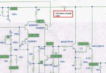
Re: The input can be a little different.... what do you see that cannot be good here.
I already did that modification with a 10ohms, gladly i had planned
it when making the pcb... It's an increase in quality regarding grounding-issues ! (Measurable)
I will show later in detail, after having listened to it...
BTW, i have/had no audible noise/hum, have you ?
Mike
destroyer X said:Can you explain please?..... this is used in some very good amplifiers....noise is zero in those that use this circuit.
Regards,
Carlos
I already did that modification with a 10ohms, gladly i had planned
it when making the pcb... It's an increase in quality regarding grounding-issues ! (Measurable)
I will show later in detail, after having listened to it...
BTW, i have/had no audible noise/hum, have you ?
Mike
I am taking a rest, as i have only your thread in the main page...so... using Radio
And producing more friends, all wide wold Hams.
From 25 to 30 Megahertz, with my modified radio...i am listening all wide world in SSB.
But i will tell you a secret....schhhhh!...do not talk people....yeah!...secret!
I found a wonderfull site in old Yugoslavia....do not know exactly the place...Servia i think.....hummmm...they had troubles some time ago...but i found one of those PHD Doctors...heavy glasses.... hair a little bit confused...those that loves to complete Einstein calculations!!!!...hehe...i asked him please to post one schematic....he answered:
I have some...not too much! (more than 500!)
- Can i have some Doctor Bora!
- Yes, i will send you some.
Well...i received 12 schematics!!!...all them different!!!...and he said that already lost the counting about the schematics he used to produce.
Now will wait him to say that i can publish.... he has not time to organize schematics...and no room enougth to take care of enormous schematics quantities..... he told that is using a refrigerator.... an old one to put some papers...ahahahaha....this one is a gênius!
regards,
Carlos
Attachments
The last language DoKtor Bora learned was Tibetan
Can you imagine the guy?
Could not complete Intelectual Quocient measurements....the old formula to calculate was not good.
He jumped out of the range....ahahahaha!
I am kidding...but not too much....Put that name in your memory...the man is special..... BORA
Carlos
Can you imagine the guy?
Could not complete Intelectual Quocient measurements....the old formula to calculate was not good.
He jumped out of the range....ahahahaha!
I am kidding...but not too much....Put that name in your memory...the man is special..... BORA
Carlos
Attachments
Yes Bob3.... this is the man.... will have a thread.
Thank you to publish the link, already made my first procedure..thanks...one less to me.
hehe
fast in the trigger Bob3
Carlos
Thank you to publish the link, already made my first procedure..thanks...one less to me.
hehe
fast in the trigger Bob3
Carlos


Really pretty square wave...hehe
This is passion..... those things are hard to explain.... someone turn full of passion watching a square waveform.
Hummm....what do you think if she turn sinusoidal....hummmm?
Well.....there are people that prefere triangle.... triangle wave shape...hummmmm.
ahahaha....
cheers for your square wave Miky...uncle charlie are observing that you are happy...you deserve...you made a good amplifier, and cooperate with our diy friends....they will feel good listening.
regards,
Carlos
I am sure that Michael is catching the right end of the rope now ... 😉
BTW, what was the repetition frequency in http://www.diyaudio.com/forums/showthread.php?postid=734246#post734246 Mike? Or time per division?
BTW, what was the repetition frequency in http://www.diyaudio.com/forums/showthread.php?postid=734246#post734246 Mike? Or time per division?
Ooops, small detail...
Frequency is ~11khz, made with a 2bjt-multivibrator and a buffer.
This gives 10us/xdiv. ydiv was 2v as i remember.
Slewratelimit is not reached yet. SR measured ~20v/us, this is no
record-number, but seems way enough.
My dummyresistor is not big enough to make photo of this measurement,
but looks identical.
Mike
- Home
- Amplifiers
- Solid State
- Explendid amplifier designed by Michael Bittner, our MikeB