> I also think that the very balanced operation of this topology is the main reason for its good sounding.
If I am looking at the right schematics, then only 1st & 2nd stage are balanced ??
Why not include a bridged output stage to make it fully balanced?
(Can half the supply voltage as a bonus.)
Patrick
If I am looking at the right schematics, then only 1st & 2nd stage are balanced ??
Why not include a bridged output stage to make it fully balanced?
(Can half the supply voltage as a bonus.)
Patrick
different balance being discussed.EUVL said:> I also think that the very balanced operation of this topology is the main reason for its good sounding.
If I am looking at the right schematics, then only 1st & 2nd stage are balanced ??
Why not include a bridged output stage to make it fully balanced?
(Can half the supply voltage as a bonus.)
You are referring to the balance between the inverted and non inverted input to output signals/impedances.
We were looking at the balance of current flows in the two halves of each of the LTPs.
Adding an inverted output stage to the other (unused) half of the VAS stage does nothing to improve the front end.
Then you have to add in the balanced inputs and reconfigure the feedback and input filtering to achieve compatability with balanced source impedances.
> We were looking at the balance of current flows in the two halves of each of the LTPs.
I thought LTPs are supposed to be used with balanced current flow, or I misunderstood you completely ?
> Adding an inverted output stage to the other (unused) half of the VAS stage does nothing to improve the front end.
No, but it helps to reduce distortions from the back end by cancelling even harmonics.
> Then you have to add in the balanced inputs and reconfigure the feedback and input filtering to achieve compatability with balanced source impedances.
That would not be so difficult, I would have thought ?
Cheers,
Patrick
Oom Nico,
also got any headings to the schematic of that beautifull discrete Radical-Audio-Synthesis headphone amp ?
also got any headings to the schematic of that beautifull discrete Radical-Audio-Synthesis headphone amp ?
Hi Mike,
Personally, I tend to use red LEDs. A two transistor set up might be as good except that the collector impedance becomes higher as you increase the emitter resistance. So a red LED would be better (higher impedance) in that regard. A circuit using a zener would be better still but may not track thermally as well.
-Chris
Yes!In my experience LED-voltage is ~1.87v at ~2ma.
So is the red LED / bjt. Just stick them together as they will thermally track very well. Try it if you have any doubts. I can't say about PSRR, but I can not imagine why they could be any difference.In my experience the 2bjt-ccs has a higher psrr. Also it is thermally stable
Personally, I tend to use red LEDs. A two transistor set up might be as good except that the collector impedance becomes higher as you increase the emitter resistance. So a red LED would be better (higher impedance) in that regard. A circuit using a zener would be better still but may not track thermally as well.
-Chris
jacco vermeulen said:Oom Nico,
also got any headings to the schematic of that beautifull discrete Radical-Audio-Synthesis headphone amp ?
Howzit Jacco, which one. I have done some - Ozgur has built some SE class A. I also gave him full symetrical complementary class A. There is also the tube/mosfet clone. You interested?
BJT CCS:
I have set the current to 10mA (I belive)It feels like I´m fumbling in the dark how big this current should be.
And how much the gain will drop with R5,R6 340 ohm,or leave it at 680 ohm.I think the gain of the stock amp is on the high side,at least connected after the DEQ2496,so I don´t mind a little lower.
Advise..
I´ve used Led CCS in tube amps with good results (not measured)
Anyway,it would be easier with a BJT,as I am NOT planing on removing the amps from the chassie.
Just change Q7,paralell the involved resistors,and use the sockets/adapter for Q1,Q2.
And not to forget C1 and R14..🙂
Hi Ryssen!
I can't view file "symasym AAK J-fet,2bjt-ccs.s#2"
I don't know what program can view it.
Bye!
I can't view file "symasym AAK J-fet,2bjt-ccs.s#2"
I don't know what program can view it.
Bye!
This one:ftp://ftp.cadsoft.de/eagle/program/4.16r2/eagle-win-eng-4.16r2.exe
Sorry,change file ending to .sch
I will fix that!
New download!
Sorry,change file ending to .sch
I will fix that!
New download!

I just checked, and it seems those files are from a cracked version of Eagle. We do not condone the use of pirate SW, and you use these files at your own risk.
Mike,
Could you tell me if 0R33 for R27/28 would make much difference in sound? I ordered the wrong values but would like to use them anyway.
Thanks
Luis
Could you tell me if 0R33 for R27/28 would make much difference in sound? I ordered the wrong values but would like to use them anyway.
Thanks
Luis
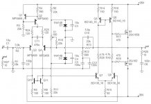
Nico Ras said:Blast from the past, I recall mid 90's, using lateral mosfets should anyone be interested in replacing the output with MOSFETs.
Can anyone explain how the idle current is set on this one?
I don't know if I get right but to me it looks like the current
is set by the voltage across R18, which depends on the current
in the LTP , which depend on the voltage across R15, which depend
on the common mode voltage on the collectors of Q10-Q11, which
depend on the current in the first LTP, i.e the current source Q1-Q2.
Does it mean that Q1-Q2 should be connected to the heat sink
for thermal stability?
Antother difference to the Symasym is the absence of the cascode
in the second LTP. Is the cascode used to increase the gain in the
second LTP?
/Peter
Attachments

'scuse the possibly dumb question, I searched but it's a difficult thing to search for effectively...
I have a spare 2x39v toroidal transformer looking for a project, which gives DC in the mid 50's. Can a SysAsym be constructed with 55v. rails? I'm sure someone must have asked for something similar (along with the usual spate of requests for 180v rails or 3000WPC output), but I can't find the time to read 70 pages of this thread to find out. I don't really care about output power, I just want to recycle my junk into worthwhile amplifiers.
..Todd
AAK's version is spec'd for 50V rails. Should be OK with 55, but ask on this thread: http://www.diyaudio.com/forums/showthread.php?postid=1179242#post1179242
Re. My Symasym
Hi Mike, I've just concluded my own symasym. It's sound better than any earlier version I have made. But I have to admit that I have used faked C5200/A1942, B649,D669. And I've got genuine 2N5087, MPSA92, C4793,A1837 from Digikey. I have push the amp to full load with a 300VA, 42V transformer, it survives with no harm, no distortion. I want to know how these faked part will affect my amp. If I replace those faked ones with genuine, how long will it improved. Now I have nothing to care about the VA characteristics of those fakes, but their speed.
Further more can you tell me about the effect of low bandwidth device (transistor) on the amp performance.
I'm attaching here my final works, please leave some comment
Regards
Attachments
printed curcuit design
I attached here the pre driver pcb of my 2 channels symasym that is working please tell me if I was doing smt wrong in circuit designing. Because it's quite expensive to have my PCB printed so I have to use up all the space of both sides. This pre dirive card is design for 2 channels, supply with +/- 66V regulated, this will require a flat heatsink of 5x8cm and 0.4cm thick. The DC servos is optional, I have it done in a thumb nail card and solder in the main card. I need a +/- 15 V supply for the DC servo. Because my 2sk30A is so poorly matched and the DC offset stay high of some 1V. I useed TL072 and keep them at 2-6 mV.
Quiecent current was put at 80 ma for each SC5200/SA1943.
The output pcb was first design to work at +/- 75V with 3 pair of 2SC5200 an a double darlington, then reduced to 2 pair and single darling ton stage; the small transistor was short-circuited. 2 Bias transistorswas replaced with a single darlington trans, some 2sd1275. This pcb sit on a large heatsink where the transistors was mounted and the trans pins pointed next to the holes
Attachments
- Home
- Amplifiers
- Solid State
- Explendid amplifier designed by Michael Bittner, our MikeB