Very good to tell our real problems...the assembler problems Mr. John Mateus.
Christer may be rigth.... looong wave lenghts because they reflect in those mirrors...up and down and this corrected the sonic
difraction of the gas environment filled with oxide.
Ahahahhaha...good that mirrored amplifier...i already did that too.
And Christer suggestion is fine.
regards,
Carlos
Christer may be rigth.... looong wave lenghts because they reflect in those mirrors...up and down and this corrected the sonic
difraction of the gas environment filled with oxide.
Ahahahhaha...good that mirrored amplifier...i already did that too.
And Christer suggestion is fine.
regards,
Carlos
Hi John, this is really a funny story, must have been tough consequently rotating the devices, especially the outputs... 🙂
Now you have the unique distortion free symasym, as it is mirrored the electrons were spinning to the right when they were distorted first, now they become left spinning and cancel out the distortions ! 😀
Mike
Now you have the unique distortion free symasym, as it is mirrored the electrons were spinning to the right when they were distorted first, now they become left spinning and cancel out the distortions ! 😀
Mike
Hi Mike
That's it Mike, you interpreted the electrons theory perfectly well.
This is the explanation why the amplifier sounds so GOOD.
The only ones I didn't have problems with were the outputs as
they are TO3. Wires go anywhere!
Cheers
That's it Mike, you interpreted the electrons theory perfectly well.
This is the explanation why the amplifier sounds so GOOD.
The only ones I didn't have problems with were the outputs as
they are TO3. Wires go anywhere!
Cheers
Actually, when I think about it, wouldn't the simplest way out have been to just turn the boards upside down and solder on the component side? Then there would have been no need for placing the components mirrored. But on the other hand, who could resist the challenge of getting it right when having to think reversed? It is probably a good exercise for the brain. 🙂
It was definitely a brain teasing experience, never happened
before.
But what's important is the result, A ok!
before.
But what's important is the result, A ok!
If i was Mr. John Mateus i would listen up side down
As sound is inverted...ahahahahahha
Kidding, of course...no one is so idiotic this way.
regards,
Carlos
As sound is inverted...ahahahahahha
Kidding, of course...no one is so idiotic this way.
regards,
Carlos
Hi MikeB!
Yesterday I ran 1 channel of symassym, and my zobel started to heat up!
Does it mean that this channel gets heavy hf oscillations?
The trace with ground was hot too…
As you know I used BD244 instead of MJE15031, I guess that my Sankens are fakes because I bought them for ~2EUR/pcs.
Quiescent current is set ~400mA, supply voltage 30,5V=DC.
I did not use the output coil, and feedback capacitor 3.3pF is unfortunately ceramic…
What do you think, what caused those symptoms?
Anyway I plugged the CD at the input, and the trebles were not false, but the music at max pumped the volume was not very loud…
padamiecki said:and 600mVdc at 4 ohm at the output, strange, because I carfully matched the transistors
Hi padiamecki, i am sorry to hear that, the zobel heating up is a definitive sign for oscillation. I suspect the very slow bd244 causing that, it might introduce a heavy phasehift. I really recommend at least the MJEs as drivers. 2 Euros for the sankens ? Thats indeed to cheap...
As long as it is oscillating you can't expect any good sound from symasym.
The DC-offset is normal for an oscillating amp because of different speeds for "complementary" transistors.
Mike
As long as it is oscillating you can't expect any good sound from symasym.
The DC-offset is normal for an oscillating amp because of different speeds for "complementary" transistors.
Mike
Hi padamiecki, some questions...
Have you already double checked all soldering/devices ?
Did you change the feedback resistor network for lower gain ? (does not work without the REs in input diffamp)
Are changing the output devices and skipping the output coil all changes ?
Mike
Have you already double checked all soldering/devices ?
Did you change the feedback resistor network for lower gain ? (does not work without the REs in input diffamp)
Are changing the output devices and skipping the output coil all changes ?
Mike
MikeB said:Have you already double checked all soldering/devices ?
Did you change the feedback resistor network for lower gain ? (does not work without the REs in input diffamp)
Are changing the output devices and skipping the output coil all changes ?
I have made the version direct connected to CD output, not the version steered from the preamp... I did not used R16 nor R19, and R29=22k, C14=3,3pF.
MikeB said:padamiecki, is there some crisis on the polish forum with not working produced PCBs ?
Yes, some kind of problems... Produced PCB links B with C of one of the output devices, Zobel condenser is linked, Zobel resistor links the output to the ground...
But it is not hard to ommit those mistakes by soldering some parts over the PCB and cut one connection on the PCB, and I am sure that I have done this properly (I heard the amp!!!), and my problems seems to be caused by low quality/slow transistors.
Yesterday I tried to lower quiescent current, but it was impossible... When I set R22 on max and even set R24 value on 1.5k the current dropped only few mA.
Anyway I have to leave this project for the vacation, I will be back ~September and suppose that I will write you that amp works perfect!
PMA said:.... but we do have profi PCB boards without any errors ......
😀
Padamiecki, (Is Pawel your name ?), this "quiscent current" is cross conduction caused by the oscillaton, you can't bias it out. It will stop when oscillation stopped.
Happy vacation !
Mike
Happy vacation!Mike [/B]
Cannot stop thinking about it, when be back will looking like NP 😎
Hi Mike,
I’m interested in building your symasym amplifier as a part of my new active speaker design. 2 way speakers are already there, hand built by me, for now using standard speaker crossover.
What moves me to built symasym is that I’m already familiar with excellent sound of this topology, no need for exotic and/or expensive parts, and the fact that I already have most of the styroflex capacitors needed.
To be honest, I didn’t quite like PCB already presented. So I’ve decided to make my own with few modifications. Picture is attached.
As for the schematics, mine will be different from yours in these few details:
1) 18k resistor at the very input of the amplifier. Previous stage needs 10k for input impedance of the next one, so that’s the reason.
2) 2 x 22uF low esr or some audio grade electrolytic capacitors, connected as bipolar capacitor, just in case I can’t get WIMA MKS-2 4,7uF capacitors.
3) 1M resistor to keep those electrolytic caps polarized. Not quite necessary, but may be useful as an option. I’ve seen it here and there so maybe I’ll try.
4) Q1 and Q2 – BC547C as Mr. Pavel used. Can’t get MPSA18, and BC’s are readily available,
5) Q7 and Q8 – BC547 as well.
6) Since I don’t want high gain amplifier, I’ve added emitter resistors to Q1 and Q2. 33 Ohms is the value.
7) To lower gain, R30 is increased to 1k.
8) Because of the previous measure, C19 can be decreased to 220u/16V low esr type.
9) C14 will be soldered beneath the PCB, in parallel with R29.
10) C3 and C4 are going to be reduced to 220pF since I already have those and Mr. Pavel successfully used them as well.
11) Instead of mentioned output transistors, I’ll be using Rotel’s favorites – 2SD1047/2SB817, simply because I already have them. (In short: SANYO triple diffused planar Si transistors, AF 60W output applications, 140V/12A/100W, hfe 60-200, 15MHz, Cob 210pf (300pF for PNP type), TOP-3 case).
12) Their emitter resistors will be 0,33 Ohms since I already have those.
13) I won’t be using R7 with inductor.
14) I won’t be using fuses as well.
Any way, before venturing myself into yet another behind-my-wife’s-back financial project, I’d like to hear your thoughts of PCB design I’ve done, and of the changes introduced.
Best regards,
Nick
Attachments
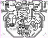
Hi Nick, nice work, but a few issues:
- if you reduce the 22k at input, you MUST also change r29 from 22k to 18k, otherwise you get a quite "large" DC-offset
- bipolar elyt at input is not really necessary, simply put + pin to the input pin, - pin to base of q1
- You somehow swapped -vcc and +vcc, the 680ohms from input diffamp are connected to negative rail ? This way the amp will not work.
- Where's the 10ohms connecting signal-gnd to normal gnd ?
- Grounding, like i did in v5.2, you have splitted postive and negative ground to the elyts, now you have large currents with half waves flowing around the frontend inducing large even harmonics.
- You shouldn't skip the fuses, they have 2 purposes, one is to keep the amp from causing fire in case of failure, and their resistance in combination with the 1000uF form a low pass filter to the voltage supply.
- i placed the output devices as close as possible to the bd139 to get better thermal tracking.
Without the fuses and with the 2 groundwires it might be better to skip the 2 x 1000uf and their bypass caps.
As the speaker wires are likely to get very short, skipping the output coil is no problem.
I will take a closer look this evening, i had not much time yet.
You have at least one issue that will make the amp not functional.
regards,
Mike
Hi Mike,
Thanks for your answers.
Regarding 18k resistor - this one is in front of the capacitor thus not affecting DC bias of the amplifier at all. This way, 22k stays as it is.
You're right about swapping +/- supplay rails. It's a typo. Those lectrolytic caps should also be reversed. Sorry. No matter how much checking things something always pass you by.
There is no resistor between grounds since I've never used them in my amplifiers and never, ever had any problems with buzz or hum. They were all dead quiet at all levels. Don't know if it's going to be a problem here.
About capacitor ground - do you mean that electro magnetic field of these PCB traces will be causing me troble? If this is the case, it's very easy for me to connect these grounds together (except signal ground). My intention was to lead these grounds with separate wires to the star ground. So now I'm puzzled.
Huh, about the fuses. I don't realy like them but I might do as you suggest. I'll place them on the board.
About output trannies position. Yes, I'm aware of the fact that they are a litte bit further away from BD139, but heatsinks are going to be large enough to compensate this. So far all my amps had trannies placed in this manner and didn't cause me any trouble.
OK, these are my thought for now. I'll change the PCB later regarding PSU orientation issue.
Like to here more of your thoughts.
Thanks and best regards,
Nick
Quattor said:
About capacitor ground - do you mean that electro magnetic field of these PCB traces will be causing me troble? If this is the case, it's very easy for me to connect these grounds together (except signal ground). My intention was to lead these grounds with separate wires to the star ground. So now I'm puzzled.
Hi, you have made second star at the caps 1000/50
- Home
- Amplifiers
- Solid State
- Explendid amplifier designed by Michael Bittner, our MikeB