That discussed driver tech which is interesting but I ment why don't CD seem to reduce above 2-3k?
I.e. not a KEF specific question ...
//
I.e. not a KEF specific question ...
//
A bit more data regarding source impedance and distortion—
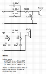
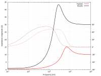
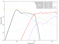
I posted this on ASR a while ago, but I'll re-post some of it here. My big DIY 2-ways originally had the drivers directly wired to the amplifier outputs (voltage source) with all filtering done digitally. More recently, I decided to experiment with adding passive networks to increase the source impedance at high frequencies.
Schematic, lookback (source) impedances, and filter magnitude responses:
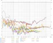
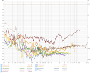
Measured distortion, 86dB SPL at 1 meter; first is voltage drive, second is with the passive networks:
And again at 96dB SPL:
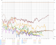
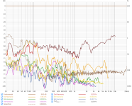
The reduction of odd-order distortion appears to be largest at lower drive levels in this case. At 86dB, H3 and H5 drop some 10dB in the top octave of the woofer's passband (500Hz-1kHz). The tweeter's H3 drops ~5dB at 2kHz and above.
I posted this on ASR a while ago, but I'll re-post some of it here. My big DIY 2-ways originally had the drivers directly wired to the amplifier outputs (voltage source) with all filtering done digitally. More recently, I decided to experiment with adding passive networks to increase the source impedance at high frequencies.
Schematic, lookback (source) impedances, and filter magnitude responses:


Measured distortion, 86dB SPL at 1 meter; first is voltage drive, second is with the passive networks:


And again at 96dB SPL:


The reduction of odd-order distortion appears to be largest at lower drive levels in this case. At 86dB, H3 and H5 drop some 10dB in the top octave of the woofer's passband (500Hz-1kHz). The tweeter's H3 drops ~5dB at 2kHz and above.
TNT: "why don't CD seem to reduce above 2-3k?"
You have to consider why current drive works to reduce distortion. The change in inductance with voice coil position results in a change in impedance. The motor force is proportional to current. So with voltage drive the change in impedance results in a change in current in the motor coil (voice coil) as the coil position changes. With current drive the change in inductance, resulting change in impedance has no effect on the current. This is the mechanism for reducing distortion. At higher frequencies the displacement of the motor is so small that the inductance, impedance and current for voltage drive do not change much so this component of the distortion is already very small so a reduction isn't possible.
You have to consider why current drive works to reduce distortion. The change in inductance with voice coil position results in a change in impedance. The motor force is proportional to current. So with voltage drive the change in impedance results in a change in current in the motor coil (voice coil) as the coil position changes. With current drive the change in inductance, resulting change in impedance has no effect on the current. This is the mechanism for reducing distortion. At higher frequencies the displacement of the motor is so small that the inductance, impedance and current for voltage drive do not change much so this component of the distortion is already very small so a reduction isn't possible.
Last edited:
That's probably a timely reminder to use multi-tone / IMD type tests. Mid-to-high frequencies may not contribute much to cone displacement, but they're nearly always riding on top of some lower frequencies to start with.
That's only part of it, and probably not the main factor for mid band harmonic distortion. At frequencies where excursion is large, the inductive component of the electrical impedance is small. At frequencies where the inductive component is dominant, the excursion is small. Inductance as a function of voice coil current, Le(i), is more significant in this case.The change in inductance with voice coil position results in a change in impedance.
As @abstract mentioned, the effect of Le(x) will show up much more in multitone measurements.
Very informative thread here! I would like to add that some consideration when designing passive crossovers can also improve distortion. Allowing the driver to 'see' a higher impedance in the midrange to reduce distortion. Very often a midrange need some padding due to baffle step, and one can try designing the crossover to allow the midrange to see a higher impedance. Same goes for woofers in 2-ways. Not optimal, but just considering it in the crossover design will probably improve things.
Here is a no-frills 5.5" midwoofer from this speaker
I measured it previously here
This time we see what current drive and a series notch filter can do.
Since one of the speakers has all the electronics, and the other speaker has none, it was easy to use this 2nd one as a test box.
First up we drive with a exponential since sweep at 2.83V, then put a 10 ohm resistor in series and drive again with 2.83V. As expected the SPL goes down. So we equalize it ("DEQ") with software, and drive it again to match the original SPL.

Now we can compare harmonics between the 2.83V drive and the 10 ohms series resistor + DEQ driven model:


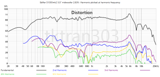
Next we investigate the effect of a passive series notch filter. All harmonics are plotted at the harmonic frequency to help see the effect.
Click the thumbnails to see the difference:
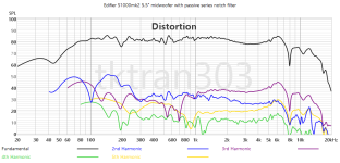
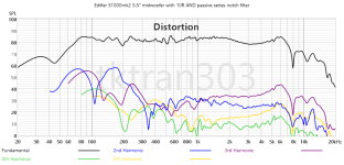
Finally let's bring it all together-
What a digital EQ can do, in a traditional active speaker:
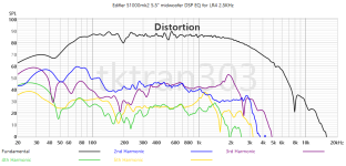
What a passive notch filter and 10R resistor can do:
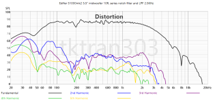
Here it is in dB down, at equivalent to 86dB /1m
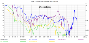
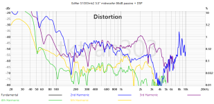
Appendix: impedance trace with the 10R resistor in series as well as the passive notch filter.
Conclusion- Active has advantages. Passive has advantages. We can use the best parts of active (crossovers by mouse clicks) and best parts of passive (reducing harmonic distortion) all together!
To put it another way, the active fanatics were right (convenience, cheaper) and the passive fanatics were right (it may sound better)
They/we are both right <-> They/we can be friends!
I measured it previously here
This time we see what current drive and a series notch filter can do.
Since one of the speakers has all the electronics, and the other speaker has none, it was easy to use this 2nd one as a test box.
First up we drive with a exponential since sweep at 2.83V, then put a 10 ohm resistor in series and drive again with 2.83V. As expected the SPL goes down. So we equalize it ("DEQ") with software, and drive it again to match the original SPL.
Now we can compare harmonics between the 2.83V drive and the 10 ohms series resistor + DEQ driven model:
For this midwoofer, at this SPL, 82-85dB, there seems to be about 5dB reduction in harmonics H2-H5 in the midrange frequencies
Next we investigate the effect of a passive series notch filter. All harmonics are plotted at the harmonic frequency to help see the effect.
Click the thumbnails to see the difference:


Finally let's bring it all together-
What a digital EQ can do, in a traditional active speaker:

What a passive notch filter and 10R resistor can do:

Here it is in dB down, at equivalent to 86dB /1m


Appendix: impedance trace with the 10R resistor in series as well as the passive notch filter.
Conclusion- Active has advantages. Passive has advantages. We can use the best parts of active (crossovers by mouse clicks) and best parts of passive (reducing harmonic distortion) all together!
To put it another way, the active fanatics were right (convenience, cheaper) and the passive fanatics were right (it may sound better)
They/we are both right <-> They/we can be friends!
Attachments
Last edited:
- Home
- Loudspeakers
- Multi-Way
- Experiments with the current drive