The attached schematic shows the auxiliary components used to tune and gain some understanding of the subwoofer system which interferes with sound waves in a room corner. Here's how its done;
1. Open switch #1 at Vout of the main power amp. Minimize the 25 Ohm pot at its non inverting input.
2. Select a low frequency [55 Hz] at the sine signal generator, and feed it at a low voltage level to the Aux PA.
3. Move switch #2 at the output of Aux PA from OFF to Direct. The subwoofer hummed.
4. Measure with an AC multimeter the voltage drop across one voice coil; say got 30 mV. Both coils had an identical voltage drop.
5. Close switch#1. The voltage across either voice coil drops. So increase the voltage input to the main power amp with the 25 Ohm pot so as to restore the original 30 mV across either voice coil. The system is set at this reference state which maybe viewed as a bootstrap.
6. Connect the leads of a scope at Vout of the Main power amp and open its switch #1.
7. Move switch #2 at the power output of Aux PA to the Acoustic setting. This power amp now drives a 3-way loudspeaker in the room where I've put it for listening to music.
8. Increase power to the 3-Way loudspeaker such that the scope [at Vout] registers 50 mVp-p at Vout of the Main power amp.
9. Close switch #1 at Vout of Main power amp. The extent and nature of the acoustic interference is readily viewed on the scope.
10. The system at hand was most sensitive between 55 and 65 Hz to cause interference.
On the web one may view dynamic simulations which depict standing waves.
1. The scope showed behaviors of acoustic interference like those on the web at frequencies in the range of 55-65 Hz.
2. Another interesting behavior of the corner system was at one single frequency. The parent 50 mVp-p signal before interference collapsed to ~10 mVp-p in an oscillating manner with interference [switch #1 closed]. An analog SPL meter at the subwoofer behaved like a VU meter whereby its oscillating needle spanned a 1 db change.
This system is set. I stripped all of the non-essential auxiliary components and got the simpler system with the schematic shown in the previous post. Next post will address the behavior of this corner system with music rich with bass.
Attachments
I do not understand how the subwoofer hummed after step 3. Where is the subwoofer in this schematic? Voice coils #1 & #2 are not connected to the 55Hz signal, and neither is "loadspeaker in room".
I do not understand how the subwoofer hummed after step 3. Where is the subwoofer in this schematic? Voice coils #1 & #2 are not connected to the 55Hz signal, and neither is "loadspeaker in room".
The power output of Aux PA [at the left of the schematic] gets connected to the joint of the two 20 Ohms power resistors by using the Direct connection of switch#2. The other end of each 20 Ohm resistor goes to a voice coil. Thus the output current of Aux PA energizes the voice coils, and finally terminates in power ground causing the subwoofer to hum at the energizing frequency. The independent power grounds of the two amps are connected which was not made explicit in the schematic, as I took for granted.
Thanks to lhquam. His questions above plus analysis on my part enabled me to simplify the original system to the attached schematic. It shows the following enhancements:
1. Use an enclosed single voice coil woofer instead of one with two voice coils. Like the other systems, this woofer is a dynamic microphone [giant] and a simultaneous formal low frequency driver because of the application of positive voltage feedback [PVF].
2. This topology is similar to that I had used early on using PVF to drive a full range or a 3-way loudspeaker. This current system is also a powered woofer.
3. Use an iron alloy power transformer with two instead of four windings.
My enclosed woofer which sits at a room corner has two voice coils. I will connect them in parallel to make a pseudo single coil woofer.
For the time being, the two primary [120 Vac] of the toroid will be connected in parallel. Ditto for the two secondary [12 Vac] windings.
Positive Current Feedback [PCF] can be taken from the ground side of the secondary and possibly the primary windings of the power transformer.
Attachments
Schematics of PVF music application
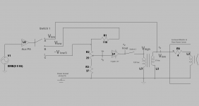
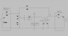
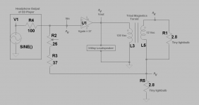
The left schematic shows the assembly to adjust the system for a bootstrap state or other. Bootstrap means the voltage of the signal picked up at the woofer [acting as microphone] is matched [reinforced] by the same value via the power amp after voltage step down. My mention of switch means to break and/or make/select connections at a connector block. The left schematic shows the method:
1. The Aux PA at switch position A directs power to the woofer and the 12 Vac transformer winding. The resultant voltage drop [V low] is noted.
2. [V low] is stepped up to [V high] at the 120 Vac winding of transformer. Its value is noted with the switch at [Vout] of power amp in the open position. Otherwise the low output impedance of the power amp will reduce its value to zero.
3. The Aux PA at switch position B next directs the same magnitude [V low] to the 110 Ohm resistor.
4. The 25 Ohm pot at the non-inverting input of power amp is adjusted to generate a value for Vout equal in magnitude to [V high] noted in the earlier step.
5. The switch at Vout of power amp is closed. The 25 Ohm pot is then fine tuned so as to reproduce the voltage of [V high] and [V low]. The 25 Ohm post is finally set and must not be adjusted further.
6. The Aux PA at switch position C next directs its voltage output [~V low/3] to the top lead of the 25 Ohm pot. This reproduces independently [ V high] and [V low] found in the previous steps.
7. The Aux PA and signal generator are removed. The 110 Ohm positive feedback resistor is lastly connected to the upper lead of the 12 Vac winding.
The middle schematic shows the above system made to play music via the woofer at the room corner or via a 3-way loudspeaker in the room. The voltage gain of assembly [V at woofer]/ [V out of headphone port] = 3.
The right schematic shows the above system made to play music at [V high] via a 3-way loudspeaker in room, and at [V low] via the same woofer at the room corner. Note that the available power output at [V high] is much larger that at [V low]. For a practical music SPL emanating from the 3-way loudspeaker in room at the listening chair, the woofer at room corner is barely audible.
The system of the right schematic has a corner woofer which interferes with sound waves, and a 3-way loudspeaker in room which is actively 'correlated' to the woofer via the same power amp.
Attachments
Still Experimenting with Positive Feedback
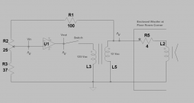
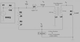
The attached schematic depicts a power amp which uses Positive Current Feedback [PCF].
1. The output voltage of the power amp [Vo], is stepped down by the power toroid which is loaded with the 2.8 Ohm [cold] non-inductive resistor of the top light bulb.
2. The magnitude of the load current through the top light bulb is sensed across the 2.8 Ohm [cold] resistance of the lower light bulb.
3. The resultant voltage drop across the lower light bulb merges with that of the music signal at the non-inverting input of the power amp like is known.
4. It follows as a postulate, that the power amp believes that its loudspeaker load is actually a non-inductive resistor.
5. Thus, PCF is independent of frequency; unlike that sensed normally via the current flowing through the 3-way loudspeaker.
6. Music through this loudspeaker sounded great.
Attachments
Still experimenting...
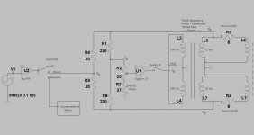
The objective in the attached schematic is to apply Positive Current Feedback [PCF] to the power amp such that the extent or magnitude of PCF is Directly and not Inversely proportional to the load impedance of the power amp. Thus, the amp gets a high value of PCF due to the woofer's high impedance at resonance, and relatively less at lower impedance values.
The action is at the secondary winding of the transformer. Note that the "sense" impedance which generates PCF is shown as either a 4 Ohms non-inductive resistor [control], or a 2-way 4 Ohm ADS L300 C loudspeaker [DUT].
1. For the 4 Ohm sense resistor, a frequency sweep in the range of 35-150 Hz [5-10 Hz increments] gave constant values for V1, Vin, Vout and Vf. The magnitude of PCF [Vf] was independent of frequency.
2. A similar frequency sweep was done using the loudspeaker as the sense impedance. The magnitude of PCF at the woofer's 100 Hz resonance frequency was 2.2 times larger in value than at 35 and 150 Hz. Basically, this experiment traced the impedance curve of the woofer.
3. The magnitude of Vout using the sense loudspeaker [at 100 Hz], was 0.723 time lower in value than the magnitude of Vout with the 4 Ohms control sense resistor at 100 Hz. This attenuation at 100 Hz was 2.8 dB.
Now to the subjective evaluation of music done as follows:
1. The signal generator was replaced with the headphone output of the CD player.
2. The sense loudspeaker was used to generate PCF and put in the corner of the room. It had a faint output.
3. The load to the power amp at its Vout was the twin of the sense loudspeaker. The twin [stereo pair] loudspeakers [load and sense] are correlated, and thus are mutually tuned.
4. The outcome was an apparent attenuation of bass, a heightened clarity in the vocals, and a sense the loudspeaker was able to manage/articulate easily complex music.
Attachments
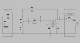
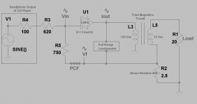
The attached schematic is for a Current Source Power Amp [CSPA] which uses Positive Current Feedback [PCF]. The details are:
1. The transconductance of this CSPA: S = 5 Amps out per Volt in.
2. CSPA drives a full range loudspeaker. Envision the Impedance versus Frequency graph for a typical woofer to describe this load.
3. Iout is a constant value when Vi is constant. But the output voltage drop across the full range loudspeaker follows the shape of its impedance graph envisioned in step 2.
4. As an example, Vout is maximum at the resonance frequency [say 45 Hz] of this woofer, and is a minimum at 100 Hz.
5. This variable Vout is stepped down by the toroid power transformer. At the secondary winding, a voltage feedback [Vf] is generated across the 2.8 Ohm sense resistor. This is Vf, and is the same as PCF,
6. The amplitude of Vf = PCF is directly proportional to the impedance of the loudspeaker. For example, the extent of PCF is a maximum value at the resonance frequency [45 Hz] of the woofer, and is a minimum at 100 Hz.
Please recall that my full range loudspeaker used in this application is made of two 15 inch drivers or musical instruments which are connected in parallel [4 Ohms]. They are not enclosed; but are bolted to the ceiling.
What about the quality of the music relative to the absence of PCF? Bass output was attenuated. The complement audio spectrum sounded clean, detailed and extended. This new sound with PCF was totally different in quality and character. I like it.
Attachments
- Status
- Not open for further replies.
- Home
- Amplifiers
- Pass Labs
- Experimenting with Positive Feedback