Re: low pass filter
After many tryings, this low pass filter is the best I tried. This low pass filter frequency is the one choosen by Cirrus in their CS4398 evaluation board. I think that this is also their recommendation.
crazyfrog said:I'm a little puzzled...When Bill write:
"You can try doubling the primary Rs to around 500 and halving the cap to around 1000pf. Some, including me, found slightly fuller bass"
That makes a 159 kHz filter.
But Legarem uses a different setup:
"On the transformer primary, I just use 220 ohms Allen Bradley carbon composition resistors (old stuff) The cap I use is 7 nF (7000 pF)
This gives a low pass filter of 51.68 khz at -3 db"
We're talking about the same DAC here...
After many tryings, this low pass filter is the best I tried. This low pass filter frequency is the one choosen by Cirrus in their CS4398 evaluation board. I think that this is also their recommendation.
Has anyone gotten one of the usb/upsampling boards to work with a 192k input source via coax? My board is marked LM-DAC3 V6. It works well with 48k and 96k inputs, but not with 192k.
Re: low pass filter
Let me try to explain my meaning. Using larger value resistors takes some load off of the dac output, increasing the bass response slightly.
What cap value you use can be totally arbitrary, what ever you think sounds best to your ears, be it 1000pf or .010uf or somewhere in between. It just changes the filter corner frequency. A 50khz corner might cause some phase shift in the upper reaches of the audio band but it isn't anything to really worry about.
Use whatever sounds good to you, that's all that really matters.
Legarem's observations are every bit as valid as anyone elses, but ultimately you have to decide what sounds best.
Best regards, Bill
crazyfrog said:I'm a little puzzled...When Bill write:
"You can try doubling the primary Rs to around 500 and halving the cap to around 1000pf. Some, including me, found slightly fuller bass"
That makes a 159 kHz filter.
But Legarem uses a different setup:
"On the transformer primary, I just use 220 ohms Allen Bradley carbon composition resistors (old stuff) The cap I use is 7 nF (7000 pF)
This gives a low pass filter of 51.68 khz at -3 db"
We're talking about the same DAC here...
Let me try to explain my meaning. Using larger value resistors takes some load off of the dac output, increasing the bass response slightly.
What cap value you use can be totally arbitrary, what ever you think sounds best to your ears, be it 1000pf or .010uf or somewhere in between. It just changes the filter corner frequency. A 50khz corner might cause some phase shift in the upper reaches of the audio band but it isn't anything to really worry about.
Use whatever sounds good to you, that's all that really matters.
Legarem's observations are every bit as valid as anyone elses, but ultimately you have to decide what sounds best.
Best regards, Bill
Re: Sumlink ST-DV709 Digtal Audio isolation transformer
Can anybody answer this please.
shuggi67 said:The new board does not have the Sumlink ST-DV709 Digtal Audio isolation transformer, is that going to be an issue I read way back in the thread that it basically renders the S/PDIF inputs weak, I have contacted the seller and she will supply one for $30!! but I can pick them up for under $10 delivered.
what does it do ? will I need it and if so how and where does it go on the new board.
And is there better ones.
Thanks
Can anybody answer this please.
Re: Re: Sumlink ST-DV709 Digtal Audio isolation transformer
One of the guys with more digital knowledge really needs to answer this.
The transformer only provides isolation to prevent ground loops and eliminate some trash from entering the digital stream. If your transport has a transformer coupled digital output, and most good ones do, then you really don't need another transformer at the input.
I am going to wire up two inputs with separate transformers so I can switch inputs by utilizing a simple front panel switch. I don't yet know exactly what they are using on the board for input circuitry so I don't know exactly what I need to change or add yet. It sure would have been nice to get a schematic with the board.
Most of the trafo manufacturers,Sowter and Lundahl for sure, make the digital pulse trafos also.
I'm sure someone in this thread has added a digital trafo by now, we need to hear from them.
Best, Bill
shuggi67 said:
Can anybody answer this please.
One of the guys with more digital knowledge really needs to answer this.
The transformer only provides isolation to prevent ground loops and eliminate some trash from entering the digital stream. If your transport has a transformer coupled digital output, and most good ones do, then you really don't need another transformer at the input.
I am going to wire up two inputs with separate transformers so I can switch inputs by utilizing a simple front panel switch. I don't yet know exactly what they are using on the board for input circuitry so I don't know exactly what I need to change or add yet. It sure would have been nice to get a schematic with the board.
Most of the trafo manufacturers,Sowter and Lundahl for sure, make the digital pulse trafos also.
I'm sure someone in this thread has added a digital trafo by now, we need to hear from them.
Best, Bill
Re: Re: Sumlink ST-DV709 Digtal Audio isolation transformer
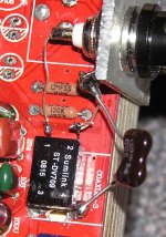
I used a Sumlink on my dac. Here is how I connected it.
The Newava S22083 is one of the best which is available for $10 at Digikey
shuggi67 said:
Can anybody answer this please.
I used a Sumlink on my dac. Here is how I connected it.
The Newava S22083 is one of the best which is available for $10 at Digikey
Attachments
shuggi67 said:Bill, Lagarem
Thanks, that pretty much answers my questions.
Another source for info is the CS8416 data sheet. It shows the trafo implementation for an aes/ebu input, just change the resistor from 110 ohms to 75 ohms for a standard SPDIF input. Notice the DC blocking cap to protect the trafo.
Bill
I have misspoken about the 75 ohm resistor, I'm reasonably sure that resistor is already on the board.
Bill Fuss said:I have misspoken about the 75 ohm resistor, I'm reasonably sure that resistor is already on the board.
Yes, it is on the board
The cap you see on the pictures goes from the BNC ground plug to the ground of the dac.
The BNC plug goes directly in the transformers without cap between the transformer and the BNC
piero7 said:Legarem, do you suggest to mount this trannie on all boards?
I wouldn't use any dac without this pulse transformer.
legarem said:
I wouldn't use any dac without this pulse transformer.
Or use the optical input
legarem said:
I wouldn't use any dac without this pulse transformer.
Plase, explain us why technically 🙂
hoverdonkey said:
Or use the optical input
I never heard good sound with optical input
piero7 said:
Plase, explain us why technically 🙂
Digital gear does RF transmission so an isolation transformer will help to get rid of RF from the transport to the dac.
With the transformer, the sound is mellower, less edgy, seems more natural.
legarem said:
Digital gear does RF transmission so an isolation transformer will help to get rid of RF from the transport to the dac.
With the transformer, the sound is mellower, less edgy, seems more natural.
Thanks! I'll sure test it! 😀
THe cap is 120pF?
piero7 said:
Thanks! I'll sure test it! 😀
THe cap is 120pF?
Something near 100pF is ok
- Home
- Source & Line
- Digital Line Level
- Experience with this DIY DAC ?