If someone is interested in doing something with the second opamp here is the label on the components:
and here the schematic (one channel - original values):
after this there are the relay, another electrolytic 2.2uF coupling capacitor, a 100K resistor to ground and the RCA socket.
Ciao
Andrea
An externally hosted image should be here but it was not working when we last tested it.
and here the schematic (one channel - original values):
An externally hosted image should be here but it was not working when we last tested it.
after this there are the relay, another electrolytic 2.2uF coupling capacitor, a 100K resistor to ground and the RCA socket.
Ciao
Andrea
How critical are the tolerances for the capacitors if implementing any of these filters? (in my case I will be following the CS recommended values).
For example the 220pF capacitors I have actually measure 230pF - anything to lose sleep over or not?
The nearest match I can get to 1000pF are: 995 / 998 / 1001 / 1008.
Thanks.
For example the 220pF capacitors I have actually measure 230pF - anything to lose sleep over or not?
The nearest match I can get to 1000pF are: 995 / 998 / 1001 / 1008.
Thanks.
How critical are the tolerances for the capacitors
The 220pF cap's you have are within 5% which is good, the 1nF are within 1% which is excellent.
The +5% tolerance of the 220pF will move the roll off frequency down by (approx) 2.5 kHz from the nominal 56kHz.
No loss in treble = no loss of sleep!🙂
I actually have insomnia at the moment but it's good to know it won't be a troubled sleepless night hahaha 😉
Thanks very much 🙂
Thanks very much 🙂
Hello!
Without any mod, is better the dac of this post (cs4398+oversampling board) or the simply "lampucera type" with cs4397?
There is someone that have both to tell the differences?
Thank you so much...
Dan
Without any mod, is better the dac of this post (cs4398+oversampling board) or the simply "lampucera type" with cs4397?
There is someone that have both to tell the differences?
Thank you so much...
Dan
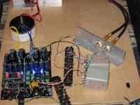
CS4398 + UTC A20
I went through some messing around with the opamp stage. I had only the first stage using a LM4562 going capless to my volume switch. It was pretty good. It had a lot of detail but wasn't as musical as I would like. I decided to not mess around with the lpf as that wouldn't change the character of the sound as much as a different output stage. A directly coupled opamp stage would work for most folks but I wanted better.
I strapped in a pair of UTC A20 line level transformers and it's great. I can't tell you if they are better than the Lundahl LL1690, but I am finally happy with the DAC. I'm not talented at describing the sound but I can almost see the music being performed now. The experimenting is over. I'm going build an enclosure when I get some time.
I've seen these UTC on ebay for as little as $140 per pair. That's pretty good.
Attachments
Hi Mush,
Can you show a closer look picture on the connection of transformer to the DAC? Theres a lot of wire hook up in there. I haven't tried these transformers before but I might give it a shot. 😀
Thanks,
Fred
Can you show a closer look picture on the connection of transformer to the DAC? Theres a lot of wire hook up in there. I haven't tried these transformers before but I might give it a shot. 😀
Thanks,
Fred
UTC
Hold on. The jury is still out.
I used Legarem's schematic from post 97 and 98 in this thread.
I am stunned at the 3-dimensionality of the sound. It feels like I can hear instruments coming from deep in the sound stage. The ompamp mask is gone, as is the edginess. Everything is musical. The problem is the lower frequencies. I can't tell if there's more control or if it's reduced in emphasis. That I usually get home very late and have neighbors and don't listen to bass heavy music doesn't help. I don't have a spectrum analyzer so I have to depend on my ears. The UTC may not be the best transformer for this. I am letting it run in for a couple of days. It will probably get better. I'd love to try the Lundahls.
When I get time in couple of months, I will try a Broskie cathode follower using a 6N6P and 6N1P.
Good luck.
Ciao -- Mint
Attachments
I am also still searching.
Funny, after about one week of listening, my ears are adapting to the sound (I am sure, it is not burning in of the circuit).
Now, I prefer the upsampling version with output trannies!
Neverless, I just soldered a board with trannies and a plate follower with a 6111WA triode.
For testing, I need to build a psu, as my Heathkit psu runs with too high heather voltage for only one tube: about 7VAC instead of 6.3.
BTW: some time ago, I made tests with Broskie Cathode follower in conjunction with a CS4397 (no transformer coupling) and I had to strong roll of in the high frequencies.
Never found the exact reason, maybe some error in my testsetup?
Franz
Funny, after about one week of listening, my ears are adapting to the sound (I am sure, it is not burning in of the circuit).
Now, I prefer the upsampling version with output trannies!
Neverless, I just soldered a board with trannies and a plate follower with a 6111WA triode.
An externally hosted image should be here but it was not working when we last tested it.
For testing, I need to build a psu, as my Heathkit psu runs with too high heather voltage for only one tube: about 7VAC instead of 6.3.
BTW: some time ago, I made tests with Broskie Cathode follower in conjunction with a CS4397 (no transformer coupling) and I had to strong roll of in the high frequencies.
Never found the exact reason, maybe some error in my testsetup?
Franz
Franz Gysi said:I am also still searching.
Funny, after about one week of listening, my ears are adapting to the sound (I am sure, it is not burning in of the circuit).
Now, I prefer the upsampling version with output trannies!
Neverless, I just soldered a board with trannies and a plate follower with a 6111WA triode.
An externally hosted image should be here but it was not working when we last tested it.
For testing, I need to build a psu, as my Heathkit psu runs with too high heather voltage for only one tube: about 7VAC instead of 6.3.
BTW: some time ago, I made tests with Broskie Cathode follower in conjunction with a CS4397 (no transformer coupling) and I had to strong roll of in the high frequencies.
Never found the exact reason, maybe some error in my testsetup?
Franz
Hi Franz
With your advice I finally bought the new dac with upsampling. I should receive it soon.
Why are you 'polluting' the signal after your transformers with an amplifying stage ?
With 1: 1 trannys, there's enough dac voltage to have correct gain.
Why are you 'polluting' the signal after your transformers with an amplifying stage ?
Polluting?
I just try to get the sonical result I wish within my audio reproduction chain.
In the sound reproduction chain cleanliness is not the absolute goal. In the recording studio, it is essential, of course.
Transformers are also far away to be linear devices, they add a fair amount of distortion.
Paul Zwicky, an ex engineer from Studer, was aware of this fact and he developped this fine circuit, including negative feedback via a second transformer.
An externally hosted image should be here but it was not working when we last tested it.
The sound of this circuit will not be polluted. Maybe a try for this DAC's output? The amplifier could also be a plate follower, feedback in a second tranny.
Want to know more? Just search for US Patent 4,567,443 and you’ll find a pdf with the complete circuit description. You find also another interesting circuits when you search for “Paul Zwicky” Patents.
BTW: often, the audio transformers have (partially) magnetized cores, due to DC measurements. This also produces unwanted distortion.
How to demagnetize it?
Add a load resistor and an oscilloscope to the secondary.
Feed in a 50Hz sinus and rise the level till saturation of the core begins. You can see it on the scope.
After full saturation, slowly reduce the input voltage down to zero.
Repeat this steps several times.
Regards
Franz
I just made another try:
My little chinese Super Pro DAC 707 (based on CS8416 and CS4398) and another Studer transformers, this time 1:1.3
The result is overwhelming: it beats all solutions, I heard up to now.
I think, the transformers I used before, ratio 1:0.62 was a bad choice, compared to this ones.
I will attach this 1:1.3 trannies soon to the "big" chinese DAC board.
Franz
/Edit
Another foto, for the size relation
My little chinese Super Pro DAC 707 (based on CS8416 and CS4398) and another Studer transformers, this time 1:1.3
An externally hosted image should be here but it was not working when we last tested it.
The result is overwhelming: it beats all solutions, I heard up to now.
I think, the transformers I used before, ratio 1:0.62 was a bad choice, compared to this ones.
I will attach this 1:1.3 trannies soon to the "big" chinese DAC board.
Franz
/Edit
Another foto, for the size relation
An externally hosted image should be here but it was not working when we last tested it.
I just fiddled around with different defined loads for the DAC, by attaching different resistors in parallel to the secondary windings of the tranny.
For this I have a little helper, an simple excel sheet to calculate the resulting impedance. I attach the sheet as zip-file. The yellow fields are input fields, the blue fields are showing the result.
With the 1:1.3 trannies, I have the best result with a 10k resistor. Based on the 100k input impedance of the following amp, this is resulting in a 5.3k load for the CS4398.
The datasheet tells me, a minimum load from 1k is needed.
Franz
Attachments
Franz Gysi said:I just fiddled around with different defined loads for the DAC, by attaching different resistors in parallel to the secondary windings of the tranny.
For this I have a little helper, an simple excel sheet to calculate the resulting impedance. I attach the sheet as zip-file. The yellow fields are input fields, the blue fields are showing the result.
With the 1:1.3 trannies, I have the best result with a 10k resistor. Based on the 100k input impedance of the following amp, this is resulting in a 5.3k load for the CS4398.
The datasheet tells me, a minimum load from 1k is needed.
Franz
Thanks a lot for this calculator
Do dacs like CS4398 have optimum load or we only have to bother about this parameter with dacs that have I/V output ?
Do dacs like CS4398 have optimum load or we only have to bother about this parameter with dacs that have I/V output ?
Yes, it seems so that also voltage output DAC's have its optimal load.
Just try it with different loads! In my case I can hear a difference with a 3.3k resistor, a 10k or without load resistor.
It seems to me, the correct load enforces in some way the middles and the bass.
The sound appears more balanced.
BTW: the calculator is not really needed for 1:1 trannies but also helpful.
Franz
Franz Gysi said:I just made another try:
My little chinese Super Pro DAC 707 (based on CS8416 and CS4398) and another Studer transformers, this time 1:1.3
The result is overwhelming: it beats all solutions, I heard up to now.
Franz, how do you feel the SuperPro 707 compares to the ebay special under discussion here? In either stock or modded configuration?
thx...
Franz, how do you feel the SuperPro 707 compares to the ebay special under discussion here? In either stock or modded configuration?
I cannot compare directly, as I have only one set of 1:1.3 trannies, wich are better than the 1:0.62.
The SuperPro 707 is much smaller, what means harder to modify. Some of the very small smd resistors and caps.
And it has a much simpler voltage regulation, some compromise compared to the discussed one. And it needs an external psu.
But it is very good, with the output trannies!
Franz
I did the modification described on the last simulation on post #229:
C1, C2, C4, C6 (1nF) are removed and C3, C5 substituted with the 82pF brown capacitors taken from the second opamp.
Here the frequency response
In green the same channel with the loop freq. resp. of the sound card subtracted.
Ciao
Andrea
C1, C2, C4, C6 (1nF) are removed and C3, C5 substituted with the 82pF brown capacitors taken from the second opamp.
Here the frequency response
An externally hosted image should be here but it was not working when we last tested it.
In green the same channel with the loop freq. resp. of the sound card subtracted.
Ciao
Andrea
Soon I can compare my DAC's with 1:1 trannies:
Should you be interested, I can offer some of them. This are very fine trannies, shielded with mu metal, the core is made of Vacoperm 100.
100US$ per pair, including shipping worldwide, flatrate.
Payment prefered by paypal.
Are you interested? Just drop a mail to
franzfgysi at bluewin.ch
Very important: use the word Studer in the subjectline, otherwise your mail will end in the spam folder.
Franz
An externally hosted image should be here but it was not working when we last tested it.
Should you be interested, I can offer some of them. This are very fine trannies, shielded with mu metal, the core is made of Vacoperm 100.
100US$ per pair, including shipping worldwide, flatrate.
Payment prefered by paypal.
Are you interested? Just drop a mail to
franzfgysi at bluewin.ch
Very important: use the word Studer in the subjectline, otherwise your mail will end in the spam folder.
Franz
First try of this 1:1 trannies:
Perfect!
Soon, I will make the same output for my Super Pro 707 DAC and then compare. But it may be you have to wait till next weekend for my opinion.
Franz
An externally hosted image should be here but it was not working when we last tested it.
Perfect!
Soon, I will make the same output for my Super Pro 707 DAC and then compare. But it may be you have to wait till next weekend for my opinion.
Franz
- Home
- Source & Line
- Digital Line Level
- Experience with this DIY DAC ?