
Received my board today, it is printed V9 now.
A quick question, I have a 120V/12-0-12/2A trafo instead of 13-0-13. I measured at the 13-0-13 power terminals and got only 11.8V as my main was only at 118V. Since the LM317 needs at least 3VDC between the input and the output. Is this too marginal? As of now, it is playing and seems to be pretty quiet.
A quick question, I have a 120V/12-0-12/2A trafo instead of 13-0-13. I measured at the 13-0-13 power terminals and got only 11.8V as my main was only at 118V. Since the LM317 needs at least 3VDC between the input and the output. Is this too marginal? As of now, it is playing and seems to be pretty quiet.
Received my board today, it is printed V9 now.
A quick question, I have a 120V/12-0-12/2A trafo instead of 13-0-13. I measured at the 13-0-13 power terminals and got only 11.8V as my main was only at 118V. Since the LM317 needs at least 3VDC between the input and the output. Is this too marginal? As of now, it is playing and seems to be pretty quiet.
Well after the recrifier you should get around 16.5V on LM317/337 inputs so that should be OK.
Also there should be a variable resistor by the LM317 so you can lower the output voltage, the opamps won't mind, but I don't think it's necessary..
Two more questions by me:
Which fuse should I get? And do I need an extra parts when I want to use the line trannies?
Which fuse should I get? And do I need an extra parts when I want to use the line trannies?
I used a 500ma fuse/fast blow (if I remember correct)
You will need resistors and caps for the primary and secondaries of the transformers, for configeration and values, have a look at what others in this thread are using with the transformers you are going to be using.
You will need resistors and caps for the primary and secondaries of the transformers, for configeration and values, have a look at what others in this thread are using with the transformers you are going to be using.
Well i found this post here: from gerarda but the build looks quite ruff.
I also found this one here by ch33ta *link*
This is looking better, but usually you need 2 trannies for the dac right?
Ch33ta, maybe you can post the values of the parts? Didnt find that yet.
I will use an extra board for the trannies and put all parts on that board. that will look a bit cleaner 😛
I also found this posts here and here, they describe the built of gerarda
Last edited:
ch33ta pic is with just one transformer connected for show/testing purpose I think.
gerada has his in a seperate box is all.
He states how he has connected them:
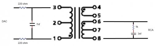
Here is a picture of my monacor implementation.
Input from DAC (before capacitors at L+/-, R+/-) through series resistors of 220 Ohm to connection 1 and 3.
In between 1 and 3 a capacitor of about 7 nF. (4,7 + 1,8 in my case).
From 6 and 8 to the output with a resistor of 1k and cap of 3nF between 6 and 8
The 7nf cap he has across 1 & 3 after the 220 ohm resistors on the primary, and the 1k and 3nf cap in series across 6 & 8 on the secondary.
gerada has his in a seperate box is all.
He states how he has connected them:
Here is a picture of my monacor implementation.
Input from DAC (before capacitors at L+/-, R+/-) through series resistors of 220 Ohm to connection 1 and 3.
In between 1 and 3 a capacitor of about 7 nF. (4,7 + 1,8 in my case).
From 6 and 8 to the output with a resistor of 1k and cap of 3nF between 6 and 8
The 7nf cap he has across 1 & 3 after the 220 ohm resistors on the primary, and the 1k and 3nf cap in series across 6 & 8 on the secondary.
Last edited:
will I found that, the two "here" links show a shematic from his build. couldnt find any experiences with his build. that would be nice to know if its good or not 🙂
Yes, I only got one Monacor for testing purposes only, of course you need two of those...
As for the filter I started with Jensen filter, not that exact values but pretty close, capacitors were the same value, the resistors were 250R and 1k...
Although, you can start with no filter, just resistors in series on DAC output and see how it sounds... Worked pretty good with my Monacor, but the sound was better with the filter, highs settled a bit...
As far as i know it's important to put the secondary filter to filter out HF noise because some people had problems with amplifiers oscillating because of that...
hm did someone have problems with symasyms?
the shematic from you is too complicated for me i guess, i dont know which parts i need an which arent required and how the wiring works etc.
maybe i should start with a simpler one. 🙁
the shematic from you is too complicated for me i guess, i dont know which parts i need an which arent required and how the wiring works etc.
maybe i should start with a simpler one. 🙁
here you go, I have just used the values in that discription - I think by that diagram 1 goes to 6 and 3 to 8, so if you connect 1 to the dac's R+(positive) 6 goes to the positive on the RCA and like wise the 3 is connected to the R- (negative) output leg of the dac and 8 to the negative of the RCA.
Attachments
Last edited:
Well ok so I will order the parts 2x from your diagram. i think this will be a first start, so i can use the line trannies and listen to my new dac soon... 🙂
damn, i can only get wima foil caps /impulse caps?
with 3,3n and 10n
can i use them or do i need exactly the same values that u posted?
with 3,3n and 10n
can i use them or do i need exactly the same values that u posted?
some posts ago I wrote about my experience with the JC-2 preamp, following the output trannies.
But, after reading the links and more about the B1 preamp, eg. a JFET source follower with a constant current source, I think, that this is more suitable to follow a 1:1 trannie, because it's gain is about unity.
So, I built up a B1 with 2SK289 and the split rail psu based on LM317. 10uF MKP at the outputs, bypassed by sowjet caps.
I will try this circuit soon.
Franz
But, after reading the links and more about the B1 preamp, eg. a JFET source follower with a constant current source, I think, that this is more suitable to follow a 1:1 trannie, because it's gain is about unity.
So, I built up a B1 with 2SK289 and the split rail psu based on LM317. 10uF MKP at the outputs, bypassed by sowjet caps.
An externally hosted image should be here but it was not working when we last tested it.
I will try this circuit soon.
Franz
Can't you get any MKT (Poyester) Caps?damn, i can only get wima foil caps /impulse caps?
with 3,3n and 10n
can i use them or do i need exactly the same values that u posted?
I can get MKH (the shop says mkt is the same?)
with the following values:
1,5 1,8 4,7 5,6 10 (and more ofc)
edit:
from ebay i can get 3,3nf and 6,8nf but 10% and only 50 pieces each.. 10 € for 4 caps is a bit much^^
and i bet they aint so good..
with the following values:
1,5 1,8 4,7 5,6 10 (and more ofc)
edit:
from ebay i can get 3,3nf and 6,8nf but 10% and only 50 pieces each.. 10 € for 4 caps is a bit much^^
and i bet they aint so good..
Last edited:
you can combine two of the 1.5s to get 3 and a 1.5 with a 5.6 for a value of 7.1(done in parallel)
It's 4.30am here I better sleep now 🙂
It's 4.30am here I better sleep now 🙂
Last edited:
1/4w and 1% is ok for resistors right?
the mkt 1,5 have 400v is this ok too? the 5,6 also has 400v..
here is a link:
http://www.reichelt.de/?ACTION=3;ARTICLE=12308;PROVID=2402
they look ugly 😀
the mkt 1,5 have 400v is this ok too? the 5,6 also has 400v..
here is a link:
http://www.reichelt.de/?ACTION=3;ARTICLE=12308;PROVID=2402
they look ugly 😀
You got me before I got to bed.
400v is fine, with resistors the larger values should give more weight to the sound, so half watt or 1 watt might be better, but quarter is OK.
Edit:Oh dear god! 😱 they are ugly!
Any combos of the Wima's that you can use?
My German is, well zero... so I have trouble getting around that site 😕
I must say goodnight now.
Last edited:
- Home
- Source & Line
- Digital Line Level
- Experience with this DIY DAC ?