Hi Jim,
I have had to fall back on my ancient EE background to wade through this mess. The datasheet specs are really not much help when interfacing trafos, except for the output impedance which I believe is 120-130 ohms. An AC load resistance doesn't make sense to start with, only they know exactly what they are talking about,and a few have contacted their engineering department and not gotten an answer.
Using the high imp trafos as you are should give you all the inductance you need but cause loading and capacitance problems, as you are well aware.
Using lower impedance output type trafos presents the problem of running out of inductance at low frequencies because of the much fewer number of primary turns, so it is a balancing act. Using series resistors between the dac outputs and the trafo lowers the output current draw at low frequencies but also raises the Fc. When the perceived output impedance the trafo sees matches the effective low frequency input impedance of the trafo, the signal is attenuated by 6db, so any series resistance added is seen by the trafo as part of the source impedance, and that raises the Fc. That is the main reason that cheap output trafos are not a very good match for a dac chip. At what point the increased output current will damage the chip is open to speculation, as some are using them directly on the output pins with no reported problems so far. I am using JT11-DMs which measure flat to my signal generator limits with 220 ohm series resistors. Other, lesser trafos will cause excess current draw at audible frequencies, but I don't have a clue as to when damage will occur so I have stayed away from commenting.
As you
load
I looked at the simulations again and there is a loading issue with using a filter with minimal series resistance. Even with 900R resistors in series with each leg, the filter cap will be shunting 2ma above cut off with a 2v peak to peak noise signal. With 250R and .01uf the load is 6ma above 100KHz. Is the level of noise that high? Probably not but it might be half of the full scale output level with the CS (or PCM) chips. Does adding an un buffered passive filter with low series resistance increase distortion in the audio band due to ultrasonic loading?
I looked at the simulations again and there is a loading issue with using a filter with minimal series resistance. Even with 900R resistors in series with each leg, the filter cap will be shunting 2ma above cut off with a 2v peak to peak noise signal. With 250R and .01uf the load is 6ma above 100KHz. Is the level of noise that high? Probably not but it might be half of the full scale output level with the CS (or PCM) chips. Does adding an un buffered passive filter with low series resistance increase distortion in the audio band due to ultrasonic loading?
The CS4398 is already filtered on chip. .01uf is way bigger than I use. If I could hear it working I wouldn't use it.
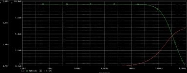
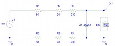
250R, .002uf filter
250R per leg with a .002uf shunt is a good compromise but doesn't really accomplish much, the -6db point is not until 440KHz. So, not really filtering much of an amps problem area anyway but still loads the dac to 1/3 the peak current level through the cap, whatever that may be, at 90KHz. Back to my original plan. Just leave the filter out.
250R per leg with a .002uf shunt is a good compromise but doesn't really accomplish much, the -6db point is not until 440KHz. So, not really filtering much of an amps problem area anyway but still loads the dac to 1/3 the peak current level through the cap, whatever that may be, at 90KHz. Back to my original plan. Just leave the filter out.
Attachments
Hmm, measurement is one thing and sound quality is something else.
Today i removed the 1k/1nF filter on secondaries of my JT-11-EMCF and the sound became brighter and sharper, for me unlistenable, so i have put it back.
I don't know the exact reason for it, but it was my experience.
Next i will remove the filter beetwen dac and Jensen and report the changes, but i am already little sceptical about removing filters...
It could be ultrasonic junk affecting your equipment, can't say for sure. I don't know what you have in your rig.
In the last days i compared the gigadac + Jensens JT-11-EMCF with some very good commercial dacs.
There is one thing immediatelly noticeable - weak bass performance and weak dynamics of the gigadac compared to other dacs.
Even gigadac with Jensens compared to gigadac+opamp has a big problem in this area.
I tried different preamps and different dacs and i think that it is a general problem.
Could it be, that a dac chip through transformers has just not enough "power" to drive preamps and that is the reason for the bad bass performance ?
any chance to make it better ? i already changed the Rs on primaries for 180 ohm, it is better than 500, but the bass is just very week 🙁
Last edited:
There are too many variables to give you a straight answer. I can tell you what I use without any negative results. I run balanced to either a Pass Aleph P or Borbely line stage to 2 Aleph J 50W monoblocks powering either Seas Thors or Troels' PMS 3 ways. The preamps have 68K input impedance or higher. On a lot of the newer poorly recorded discs the bass is so overblown it is unlistenable. On good classical or jazz recordings, everything is perfectly balanced. Articulation and speed of bass is to die for. I use the JT11-DMs which are larger than the EMs, but I can't imagine THAT would make such a profound difference.
Are you using some strange boutique interconnects or are they extremely long?
If you had access to a scope or at least a true RMS voltmeter you could check your playback performance with a test disc or other test source.
Best, Bill
Are you using some strange boutique interconnects or are they extremely long?
If you had access to a scope or at least a true RMS voltmeter you could check your playback performance with a test disc or other test source.
Best, Bill
Nothing is out of phase, the connections are as short, as possible, tried different hq carbon and metal resistors (Vishay-Dale, Beyschlag, Riken) and caps are Wima MKS-02 2.2n on primary and 1nF on secondary.
I have to do some measurement.
I have to do some measurement.
Phase
All of your comments about needing filters and having weak bass sound like you are wired out of phase. The board has a confusing layout as the signals at the first coupling caps are -++- with both positive legs for the left and right channels, next to each other in the middle. If it isn't phase then perhaps you have something bypassed that is shorting the 2.5v dc component of the dac chip output to ground through a resistor. Where are you tapping the direct output of the chips?
.
.
In the last days i compared the gigadac + Jensens JT-11-EMCF with some very good commercial dacs.
There is one thing immediatelly noticeable - weak bass performance and weak dynamics of the gigadac compared to other dacs.
Even gigadac with Jensens compared to gigadac+opamp has a big problem in this area.
I tried different preamps and different dacs and i think that it is a general problem.
Could it be, that a dac chip through transformers has just not enough "power" to drive preamps and that is the reason for the bad bass performance ?
any chance to make it better ? i already changed the Rs on primaries for 180 ohm, it is better than 500, but the bass is just very week 🙁
Last edited:
i am taking the outputs directly from a dac pcb, like on this picture:
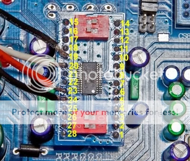
PIN 19 - Output Channel B-
PIN 20 - Output Channel B+
PIN 23 - Output Channel A+
PIN 24 - Output Channel A-
Because of the 50Hz hum i connected the minus of the rca output on the case to the minus on pcb. RCA outputs are isolated from the case.
PIN 19 - Output Channel B-
PIN 20 - Output Channel B+
PIN 23 - Output Channel A+
PIN 24 - Output Channel A-
Because of the 50Hz hum i connected the minus of the rca output on the case to the minus on pcb. RCA outputs are isolated from the case.
dc
Is the dc between each pin and ground the same?
i am taking the outputs directly from a dac pcb, like on this picture:
Is the dc between each pin and ground the same?
You have AC grounded your output signal. Your hum is coming from incorrect orientation of the trafos. Mave them as far away from the power trafo as possible and reorient them. Sometimes just a few degrees eliminates any hum.
The output transformers are nearly 40cm from the power transformer and preamp is also 40cm apart, there is no other gear close to the dac.
Without earthing there is a strong 50Hz hum.
This is my test setup:
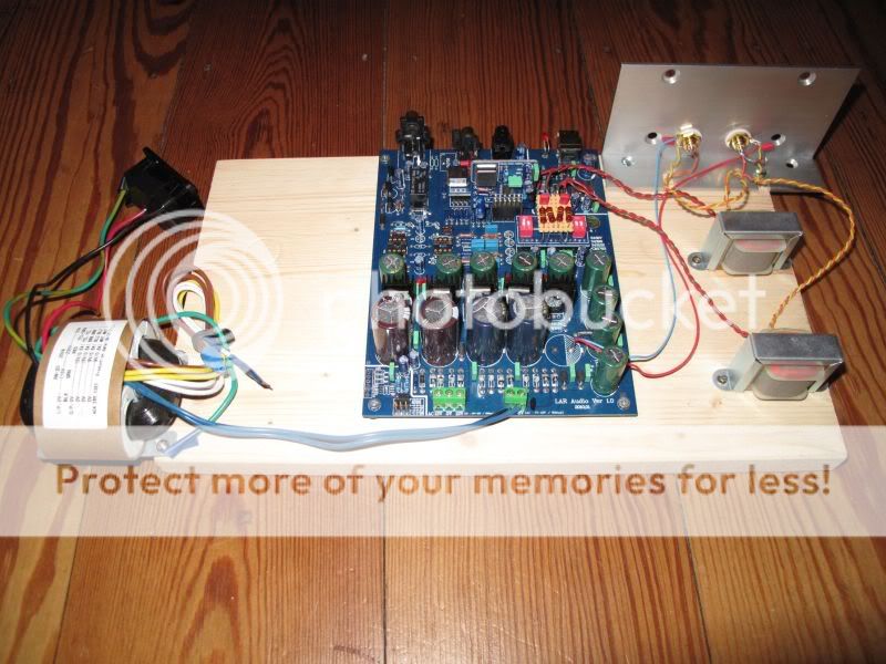
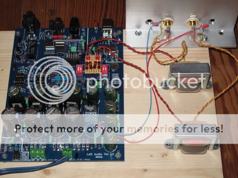
This an example how Neko Audio is placing the same transfomers (i bough mine from Neko Audio on ebay):
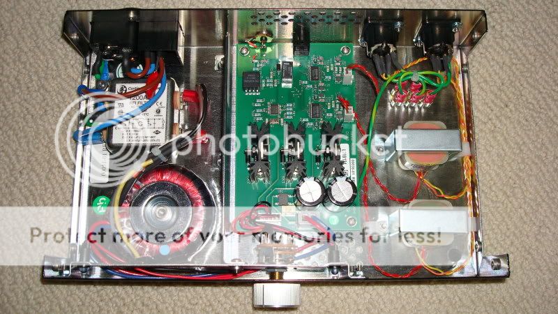
So, i assume, that my transformer are placed correctly.
Maybe the earthing is the problem, but without connecting the minus from rca output to the minus on the pcb (blue and red cable on the right, where the usb power cap was) there was a very strong 50hz hum. This hum is not present in my system, when i was connecting other dacs, SquezeboxClasic and Touch or CD-players. My system is ABSOLUTELY quiet. Very, very little noise, no hum 🙂
This is the application manual from Jensen, brown on input is +, and red is -, on the output orange is + and yellow is - , i hope i am right.
http://www.jensen-transformers.com/datashts/11emcf.pdf
This is application example how to connect a cirrus dac to output transformer:
http://www.jensen-transformers.com/as/as093.pdf
It is a different transformer, but i assume that output and input filter values are correct for my transformer.
I am a beginner, i have very little idea about electronics, more experience than knowledge, but i have already build few much more complex things which worked perfect.
This bass thing is really strange, i don't know where the bug is.
Maybe somebody can help 🙂
Without earthing there is a strong 50Hz hum.
This is my test setup:
This an example how Neko Audio is placing the same transfomers (i bough mine from Neko Audio on ebay):
So, i assume, that my transformer are placed correctly.
Maybe the earthing is the problem, but without connecting the minus from rca output to the minus on the pcb (blue and red cable on the right, where the usb power cap was) there was a very strong 50hz hum. This hum is not present in my system, when i was connecting other dacs, SquezeboxClasic and Touch or CD-players. My system is ABSOLUTELY quiet. Very, very little noise, no hum 🙂
This is the application manual from Jensen, brown on input is +, and red is -, on the output orange is + and yellow is - , i hope i am right.
http://www.jensen-transformers.com/datashts/11emcf.pdf
This is application example how to connect a cirrus dac to output transformer:
http://www.jensen-transformers.com/as/as093.pdf
It is a different transformer, but i assume that output and input filter values are correct for my transformer.
I am a beginner, i have very little idea about electronics, more experience than knowledge, but i have already build few much more complex things which worked perfect.
This bass thing is really strange, i don't know where the bug is.
Maybe somebody can help 🙂
You don't see any windings grounded on their schematic, do you. You are shunting the output signal to ground. The output is plus and minus, not plus and ground. The shell of the RCA is referenced to ground at your preamp, it should not be grounded to the dac circuit.
Please remove those grounds and turn your output trafos in a different direction, or possibly turn your power trafo a different direction.
Please remove those grounds and turn your output trafos in a different direction, or possibly turn your power trafo a different direction.
ground
Tying one leg of the output connector to the gound of the board is not the problem although you can try moving them to the pin #21 at the chip and reinstall the missing cap. I was also unable to run my transformers with the ground floating due to hum and had to do the same thing. This is the normal way to convert balanced to single ended. Sometimes you can get away with a floating ground and sometimes you cannot. It looks like your wiring is correct through the transformers. Are you sure the big cap you removed is just for the usb? You can try removing the filter and listen without it to find out if maybe it is wired wrong and causing the problem. Measure the dc voltage between each of the dac outputs and ground. They should all be about the same around 2.5v. Any differences can indicate a short or a bad chip.
Because of the 50Hz hum i connected the minus of the rca output on the case to the minus on pcb. RCA outputs are isolated from the case.
Tying one leg of the output connector to the gound of the board is not the problem although you can try moving them to the pin #21 at the chip and reinstall the missing cap. I was also unable to run my transformers with the ground floating due to hum and had to do the same thing. This is the normal way to convert balanced to single ended. Sometimes you can get away with a floating ground and sometimes you cannot. It looks like your wiring is correct through the transformers. Are you sure the big cap you removed is just for the usb? You can try removing the filter and listen without it to find out if maybe it is wired wrong and causing the problem. Measure the dc voltage between each of the dac outputs and ground. They should all be about the same around 2.5v. Any differences can indicate a short or a bad chip.
OK, first i found the source of the hum.
Usually the system need one connection to 230V ground. I checked the system - my sb touch ps do not have it, dac, preamp and poweramp also not. 230V ground was always connected to the case.
So i connected the 230V ground with the pcb ground of the dac (- pin of the usb cap) and the hum dissappeared, than i removed the connection between the minus of the rca output and pcb ground, it was no more necessary.
Than i measured frequency response 20Hz-20Khz -10dB and 0dB, it is a perfect stright line. I was thinking that the problem is solved, but than i did again the connection between rca minus and pcb ground and measured the frequency response - it was absolutely identical.
I am thinking that my problem with bass and dynamic is a "dynamical" problem. When a longer bass line is appearing, than the gigaworks dac is loosing the breath, small dac chip has not enough power to keep it playing dynamic music. A dac where opamps ps is stabilzed can deliver the necessary current in a changing dynamic music. Hmm, we will see, i lowered the primary resistors to 180 from 230 and the dac became louder.
Is there any way to measure the behaviour of the dac under dynamic load ?
Last edited:
- Home
- Source & Line
- Digital Line Level
- Experience with this DIY DAC ?