The switchs close to the CS4398 are, at the left 1-on 2-off, at the right 1-off 2-off. something to change here ?
I've looked around trying to find some info for you.
The CS8416 and CS4398 will handle 24/192 but your Torx receiver may not, you will have to look up the one you have on the board.
The CS4398 switch positions should be UP,DWN,DWN,DWN. UP is actually off, and down is on. You can only use that setting for 24/100-200 so no other format should work in hardware setting unless you would add a detection circuit to automatically pull the appropriate pins up or down.
I have the upsampling version and have not tried native high resolution signals. If you have noise from the dac with no input connected I would suspect a ground loop problem with your amp and dac.
If you only have noise problems when the input is connected then a compatibility problem exists. I don't know if we can help in that regard.
Can you be sure your source is 24/192?
Best, Bill
The CS4398 switch positions is UP,DWN,DWN,DWN on my board. In this position, all the sample rate tested with Windows 7 are working fine : I chose a sample rate, for example 192 Khz, I click on the "test" button and I hear the sound. I suppose W7 test is good : there is an other test for DTS audio or Dolby digital and when I try to test it I have a negative answer (this DAC do not accept DTS audio 😀).
My conclusion is that this DAC accept all the sample rate without changing any position on the CS4398 switch...
Regarding my noise problem, i only have noise when I connect the source (When Windows open), I hear à click on the DAC (I suppose an electronic relay opening output stage ?) and i hear the noise (slight low frequency noise, sory for my english again). No sound if the dac and my t-amp are on and the computer off. Same small noise with optical SPDIF or coxial SPDIF.
I'm sorry, that is a problem I can't help with. Sounds like a ground loop but that's impossible with optical isolation, unless you have the coax plugged in at the same time.
A great setup for RedBook users primarily.
I've been hacking on transports and greatly improved the SPDIF to the point that all the cables sound the same. I am using a full 5v reclocked SPDIF output that looks fabulous on the scope.
Now I've found something better and much simpler, provided you have the upsampling board and like it. A found a Magnavox CD2000 on ebay really cheap, cheesy player but great CDM4/19 transport. It is a non-oversampling player that uses I2S from the decoder chip to the dac chip. I tapped into the I2S lines and fed it directly into the CS8421 inputs. In my case the SAA7210 decoder is 5v out so I had to make two voltage dividers for the data and bit clock lines with Dale RN55 resistors to knock the voltage down below 3.3v,which is the max input for the cs8421. I used 1.5k and 2.2k. You simply remove the CS8416 and plug your resistors and ground into the socket. It will only work with the upsampling board installed because the cs4398 needs the clock from the cs8421.
It's relatively easy to do but study up and ask questions if you want to try it. It is another significant improvement, but it also limits the board use to I2S.
Converting a signal to SPDIF then transmitting it then converting it back to I2S always seemed dumb to me, but it is convenient.
I'm so impressed with it I'm buying another board to install in the player.
I'm pursuing my obsession with the pulse transformer on the digital input thing. This time with the Newava S22083 http://www.newava.com/pdf/S22083.pdf
Can some knowledgeable person please explain how this thing should be properly connected to the digital input?
On the PDF file the diagram on the top of the page and the diagram on the bottom of the page appear to show different pinouts(3 & 4 inversed). The only thing I'm sure about is that "1" is the "+" primary.
Also - Do I need to place caps/resistors anywhere in the circuit?
Lundahl specified a 0.1uF cap on primary to eliminate DC for their LL1572.
I contacted Newava to try and obtain some info but no one was available.
The SPDIF transformer is a good thing, you need galvanic isolation to prevent EMI/RFI from your digital source from getting in your DAC. BUT some people here say they are a bad thing. They could distort the signal, affect jitter and sound quality etc.:
http://www.diyaudio.com/forums/digital-source/18068-spdif-transformers.html
I think this occurs if the signal source and DAC are not properly impedance matched- you'd have to check signals with an oscilloscope for top performance. Your transport must have a 75 ohm output impedance and the S22083 a 75 ohm load resistor (R19 on the CS8416), all of which you probably have or can check with an ohmmeter.
On the Newava S22083 datasheet, the top picture shows the physical pin layout and the bottom is only the schematic pictorial. All that's important is Pins 1 and 3 are in-phase for this xfmer and located on opposite diagonals.
Xfmer Pin 1 to source RCA center
Xfmer Pin 2 to source RCA gnd pin
Xfmr Pin 3 to DAC input RCA center
Xfmr Pin 4 to DAC input RCA gnd pin
Try it out and try different cables too, as they have different impedances.
McCrackers, is it worth doing the whole 75 ohm thing properly and getting BNC connections for the S/PDIF input? Alternatively a 75 ohm RCA connector like the Canare RCAP series:
CANARE RJ-RU RCA (PHONO) CONNECTOR
or
http://www.canford.co.uk/Products/45-898_CANARE-RJ-RU-Flush-mount-RCA-phono-solder
This is something I intend to do. Makes sense...
CANARE RJ-RU RCA (PHONO) CONNECTOR
or
http://www.canford.co.uk/Products/45-898_CANARE-RJ-RU-Flush-mount-RCA-phono-solder
This is something I intend to do. Makes sense...
Last edited:
@ prairiemystic -
Thanks for demystifying the pinout diagrams. It's pretty much what I suspected.
Not sure if I'm doing this correctly but when I check impedance(resistance) of my source RCA output connector I get 107.7 ohms. I get about the same reading(+1 ohm) when I check at the end of the coax cable plugged in to source.
When I check my DAC's RCA input connector(exterior) I get 75 ohms. When I check the DAC input connector's other end(inside) with cable connected to source I get 45 ohms.
So what does all this mean and what, if anything, needs to be done?
@ Rich Lund - I agree. I was looking at these which are also inexpensive and available locally: Parts-Express.com:Neutrik NBB75DFGB BNC "D" Feed-Through Grounded Black | bnc bnc chassis bnc connector bnc D bnc "D"
Last edited:
The 107.7 ohm reading is okay. Coax SPDIF outputs are typically a logic gate feeding a resistor network (typ. 374 and 90.9 ohm) out to the RCA jack or SPDIF output transformer. Check the schematic of your source if you can. So you will not read 75 ohms on the SPDIF transmitter.
I connected my input trafo direct to the CS8416 (not the RCA conector,to bypass the capacistor).
To RXP0 and ground to RXN.
http://www.cirrus.com/en/pubs/proDatasheet/CS8416_F3.pdf
I think this is the best way to do it.
It works fine.
I use a well known So called High end trafo,cant remember the name right now..
To RXP0 and ground to RXN.
http://www.cirrus.com/en/pubs/proDatasheet/CS8416_F3.pdf
I think this is the best way to do it.
It works fine.
I use a well known So called High end trafo,cant remember the name right now..
I connected my input trafo direct to the CS8416 (not the RCA conector,to bypass the capacistor).
To RXP0 and ground to RXN.
http://www.cirrus.com/en/pubs/proDatasheet/CS8416_F3.pdf
I think this is the best way to do it.
It works fine.
I use a well known So called High end trafo,cant remember the name right now..
Trafo has 4 pins. One(+ secondary) to RXPO and one(- secondary) to RXN. Right? Where do you connect the other two?
@ Rich Lund - my thoughts exactly
Last edited:
Where do you connect the other two?
McCrackers - My thoughts exactly!!
Ok,here are some pics:
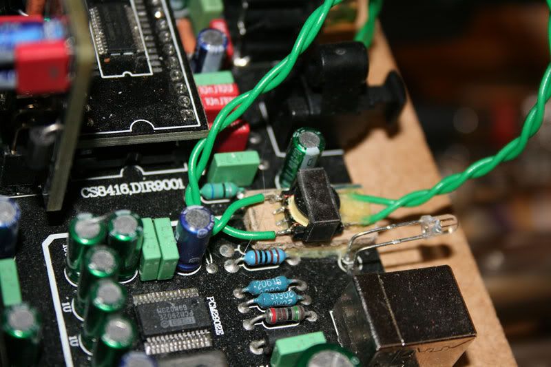
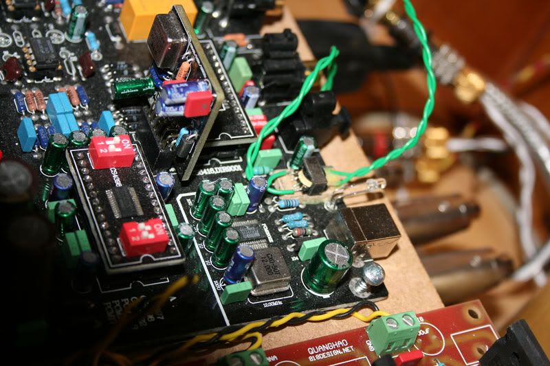
The other side of the trafo is connected to an RCA input jack (you could use RCA on the PCB,but you have to desolder the capcistor that is there originaly) that is connected to the source,(The CD or DVD player ).
The CS8416 is connected on the underside of pcb,with a twisted cable to the trafo.
Anyone can see what brand the trafo is?I have forgotten..
Last edited:
Thank's Ryssen, that's much clearer.
I have a sumlink ST-DV709, which I understand is ok but not the best. If I like the results I may get a Newava or Lundahl.
I don't suppose you know which pins are what on the Sumlink? I have tried to find a datasheet but no luck.
Another question - I see you are using Salas shunt regulators. Are you tapping in to the circuit tracks? What areas are you regulating?
Edit: I just found this info on the Sumlink:
http://www.cndiyclub.com/bbs/attachment/Fid_32/32_4_046d1802a7017be.jpg
Last edited:
No,but you should be able to messaure it,since it is 1:1 it doesn´t matter how it´s turned.I don't suppose you know which pins are what on the Sumlink?
Edit:Yes you found the schema.
Yes I have cut the tracks after the 3 original 5v regs,and connected 3 Salas regs.I see you are using Salas shunt regulators. Are you tapping in to the circuit tracks? What areas are you regulating?
@ Ryssen - Thanks for the pics. It makes more sense now. What threw me off was your previous comment "(not the RCA conector,to bypass the capacistor)"
Just finished installing the Newava. I'm listening to it right now and I'm quite happy with the sound - very clean. Connecting directly to the chip was definitely a good idea. 
If someone wants the LL1572 I'll let it go for 15$ + postage.
If someone wants the LL1572 I'll let it go for 15$ + postage.
- Home
- Source & Line
- Digital Line Level
- Experience with this DIY DAC ?