I guess if the amp is "fixed bias" that means the bias is usually adjustable via a trimpot or maybe two of per channel. If the amp is self-bias or auto-bias then the bias is set by a fixed resistor in the cathode/s of the output tubes. I don't understand why your 6P3S is hot at the seams, it might be worth checking the voltages at the plate, screen, grid and cathode of the outputs with no signal going in.
I guess if the amp is "fixed bias" that means the bias is usually adjustable via a trimpot or maybe two of per channel.
If the amp is self-bias or auto-bias then the bias is set by a fixed resistor in the cathode/s of the output tubes. I don't understand why your 6P3S is hot at the seams, it might be worth checking the voltages at the plate, screen, grid and cathode of the outputs with no signal going in.
I was actually about to dispute what you said, but I did a little Googling and realized you are correct on the different types of bias. I was going under the assumption of the literal terms "fixed", "cathode", "auto" and "manual" biasing. It's quite confusing as "fixed" bias actually means that it is adjustable! I would have made an a$$ of myself disputing you if I had not first researched it, and so I apologize ahead of time for even doubting you. I am by no means new to hifi and the terms involved, and I know what to look for in top-notch equipment, and even know when it comes to different design types, but the inner workings of said gear is still foreign to me.
As I said in a previous post, I have the proper equipment to take measurements and I would really like to know what this amp is running the various tubes at, I just don't know enough to probe under the amp without either frying something or frying myself. There's no schematics for this amp in its current state and the guy who modified it refuses to reply to my email. And quite honestly, I don't even care for him as he let this amp go with all the old, dried up original caps in it still, knowing darn well the things were well out of spec and about to die at any moment. That to me is just stupid. I certainly wouldn't waste any of my money on him, that's for sure.
There's no schematics for this amp in its current state and the guy who modified it refuses to reply to my email. And quite honestly, I don't even care for him as he let this amp go with all the old, dried up original caps in it still, knowing darn well the things were well out of spec and about to die at any moment.
Well, that's pretty normal. And for me that's a positive. It's plenty fun to take a sick and dying old amp and restore it to its former brilliance (if it had any). But the really fun part is mapping out it's circuit and understanding it, and maybe improving it a bit here an there where the manufacturing economies might have limited its quality a bit.
The safety part is easy... Assume everything you touch will kill you instantly. I recommend you wear a certified non-conductive scuba diving suit and arc welding (or hockey) gloves while working on tube amplifiers.
Both 6N3C-E and 6P3S-E are transliterated names for the very same tube. The Russian alphabet doesn't (obviously) use English characters, so these are just rough translations for 6П3C-E (the real Russian name stamped on the tube). The Russian C is equivalent to a Western S. The "П" (pi symbol) looks like an N sort of, but represents a P sound, hence the various confusing transliterations. The -E is a specialized variation of that tube. I don't recall which variation, maybe more vibration tolerance intended for military mobile vehicles (fighter jets, tanks, etc) or maybe it means longer life; 5,000 or 10,000 hours. Can't remember, but you can Google that too.... NOS NIB 6N3C-E tubes. From what I gather, they are supposed to be the same as the 6P3S-E tubes. I'll see how these compare to the ones I'm using now.
..Todd
Last edited:
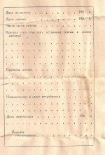
Actually, "E" means longer life guaranteed. Each military tube has a passport, with a reclamation form on the rear side, so service personnel can fill up the form and send it back indicating how long the tube served, and what had been changed in it's parameters. It was pretty tough procedure for the manufacturer, so they tried to cover their a$$es carefully. That's why specs for 6P3S-E are too relaxed!
Actually, it is a different from 6P3S tube, with vibration specific construction, and can dissipate more power than ordinary 6P3S that was mostly used in government communications equipment, but ratings specified were more relaxed.
Edit: an example of a reclamation form attached.
Actually, it is a different from 6P3S tube, with vibration specific construction, and can dissipate more power than ordinary 6P3S that was mostly used in government communications equipment, but ratings specified were more relaxed.
Edit: an example of a reclamation form attached.
Attachments
Last edited:
Mine arrived without a passport. I suspect they got on the plane disguised as a Western Electric 300B and removed their disguise in the bathroom half-way across to reveal they were actually much younger 6N2P-EV's. Now they're seeking refugee status. 
..Todd
..Todd
Last edited:
Well, that's pretty normal. And for me that's a positive. It's plenty fun to take a sick and dying old amp and restore it to its former brilliance (if it had any). But the really fun part is mapping out it's circuit and understanding it, and maybe improving it a bit here an there where the manufacturing economies might have limited its quality a bit.
The safety part is easy... Assume everything you touch will kill you instantly. I recommend you wear a certified non-conductive scuba diving suit and arc welding (or hockey) gloves while working on tube amplifiers.
..Todd
Well how would I go about mapping out the schematics for this amp, or would one of you guys here be willing to do it if I supplied detailed images?
The amp already sounds amazingly good as is with just simple tube rolling, but if there's a few places under the hood to make some improvements, I'm all for that. I'm also wondering what all would be involved in getting this amp to the point to where I could also roll EL34, 6550, 6CA7, KT88, etc, etc into it. I was told in my other "Baldwin" thread I think that the #1 pin is not used and all I would have to do is solder in a jumper from pin #8 to pin #1. I'm almost certain the PST is more than capable of handling the load of the EL34 based tubes, especially with two 5U4's running. But I can't help but imagine there has to be more to it than that as the bias would probably have to be adjusted for the other style tubes.
When I got to the safety part of your post, I busted out laughing! 😛😛
I thought someone posted an appropriate Baldwin schematic in the other thread. Follow the wires, see if it matches yours.
Converting the amp to a different tube family is probably best left until after a bunch of reading and learning and general experience. That's a step beyond tube rolling.
..Todd
Converting the amp to a different tube family is probably best left until after a bunch of reading and learning and general experience. That's a step beyond tube rolling.
..Todd
Hello,
Nice photographs.
Two or three years ago I was messing around with bread boarding Single End Triode 6L6GC’s.I did not want to spend a bunch on NOS GE’s so I bought 24 of these tubes you are speaking of, same letters and logo’s. They sounded real nice and up until then I had only seen photographs of that neat blue glow. I took the bread board apart a long time ago.
Do you think the glow is temperamental or can get a set of 4 to glow as pretty in a push pull stereo amplifier.
DT
All just for fun!
The safest way to measure voltages on pins of tubes is to get some multimeter leads with alligator/crocodile clips on the other end. With the amp turned off, you attach one clip to the pin you want to measure, and the other to ground. Turn the volume to zero (or short the inputs) and have the speakers connected as usual, or if that is not convenient, put some 4 or 6 or 8 ohm resistors across the outputs rated 1W minimum. Then connect the mains and turn the amp on, wait for a couple of minutes for voltages to settle and write down the reading. Then turn the amp off, disconnect the mains, wait a couple of minutes for the HT to bleed down, and attach the clip to the next pin to be measured. This way you don't have to be anywhere near the amp except to turn it on and off. If you have two meters you can take two readings at a time. The pins are read clockwise 1 to 8 with pin 1 being the first one clockwise from the key in the socket (and tube), this is looking from underneath the amp at the socket. Pin 3 (anode) is B+ expect around 300 to 450V on this one, pin 4 is the screen, maybe same as B+ or maybe less, pin 5 is the grid, it might be 0V or maybe -25 to -45V, and pin 8 is the cathode, which may be either 0V, or +25 to +40 or whatever. With these four voltages it can be determined if its fixed or auto-bias, and if the tube is being run within limits or not.
The safest way to measure voltages on pins of tubes is to get some multimeter leads with alligator/crocodile clips on the other end. With the amp turned off, you attach one clip to the pin you want to measure, and the other to ground. Turn the volume to zero (or short the inputs) and have the speakers connected as usual, or if that is not convenient, put some 4 or 6 or 8 ohm resistors across the outputs rated 1W minimum. Then connect the mains and turn the amp on, wait for a couple of minutes for voltages to settle and write down the reading. Then turn the amp off, disconnect the mains, wait a couple of minutes for the HT to bleed down, and attach the clip to the next pin to be measured. This way you don't have to be anywhere near the amp except to turn it on and off. If you have two meters you can take two readings at a time. The pins are read clockwise 1 to 8 with pin 1 being the first one clockwise from the key in the socket (and tube), this is looking from underneath the amp at the socket. Pin 3 (anode) is B+ expect around 300 to 450V on this one, pin 4 is the screen, maybe same as B+ or maybe less, pin 5 is the grid, it might be 0V or maybe -25 to -45V, and pin 8 is the cathode, which may be either 0V, or +25 to +40 or whatever. With these four voltages it can be determined if its fixed or auto-bias, and if the tube is being run within limits or not.
Thanks for the great tip on taking measurements from above the amp! It worked great!
Before going ahead and taking measurements, I called up my father to consult with him once more on this amp. He said that it is in fact cathode biased, NOT fixed like I thought he said.
So here's the report measurements taken a few minutes ago...
Pin #2 - Filament: -12.7v
Pin #3 - Anode: +384v
Pin #4 - Screen: +388v
Pin #5 - Grid: +24v
Pin #8 - Cathode: +33v
I'm assuming that if I took a measurement on Pin #7, it would have probably read something like +12.7v. BTW, isn't that DOUBLE the norm (6.3v)?
Oh, I forgot to mention that all these measurements were taken off the first output tube closest to the PST.
I'm assuming that if I took a measurement on Pin #7, it would have probably read something like +12.7v. BTW, isn't that DOUBLE the norm (6.3v)?
My guess is that the 2 output tube's filaments are wired in series. So if you measured the other filament pin you should get 6.35v. The 12.7v gets divided evenly between the 2 tubes.
12.7V --> tube1 --> 6.35v ---> tube2 ---> 0v (gnd).
..Todd
Last edited:
I got in the new tubes and have them running. They're a bit lacking in the bass department, but I'm sure with some hours on them (they've only been running about an hour so far), they'll open up and get a little livelier. Or at least I certainly hope so. I'll post some pics in a few.
My guess is that the 2 output tube's filaments are wired in series. So if you measured the other filament pin you should get 6.35v. The 12.7v gets divided evenly between the 2 tubes.
12.7V --> tube1 --> 6.35v ---> tube2 ---> 0v (gnd).
..Todd
Hi Todd!
That makes perfect sense and is more than likely the case. That puts the voltage spot on for all practical purposes.
Oh, and I guess the lack of bass with the new tubes was just a matter of the music I was listening to. I have some pipe organ music on right now and there's plenty of bass tickling my ear drums! 😀
The plate and screen voltages look reversed too. Might not be, but the plate is usually higher than the screen (or the same). Measure the other tube and see what you get. Is the output transformer UL or not? (i.e. 5 primary leads, or just 3)
..Todd
..Todd
Last edited:
The plate and screen voltages look reversed too. Might not be, but the plate is usually higher than the screen (or the same). Measure the other tube and see what you get. Is the output transformer UL or not? (i.e. 5 primary leads, or just 3)
..Todd
Looking at the pics of the guts, it looks like there's 3 leads going in and 2 coming out of each OT.
Okay, per your request Todd, I just took measurements of the left output tube for the right channel with the new tubes installed. The first batch of measurements were taken of the left output tube of the left channel with the old tubes.
Left CH with first set of Russian tubes...
Pin #2 - Filament: -12.7v
Pin #3 - Anode: +384v
Pin #4 - Screen: +388v
Pin #5 - Grid: +24v
Pin #8 - Cathode: +33v
Right CH with new set of Russian tubes...
Pin #2 - Filament: -10.5v
Pin #3 - Anode: +390v
Pin #4 - Screen: +399v
Pin #5 - Grid: +0.62v
Pin #8 - Cathode: +28.4v
Something definitely seems fishy with Pin #5 with the new tubes in. The only differences between these two tests is the fact that the heat and coffee pot was on this morning which may explain the lower B+ and Screen voltages, but I'm merely speculating here. That wouldn't explain the higher Cathode voltage nor does it explain the wacky Grid voltage.


Okay, per your request Todd, I just took measurements of the left output tube for the right channel with the new tubes installed.
Well, actually I meant the other tube in the same channel. Keep things simple, tackle one amplifier channel at a time. Also changing tubes will alter the operating point, so re-do the first measurements with the new tubes.
Are you measuring with the speaker connected (or a 4-8 ohm dummy load connected) and the input shorted? (input signal lead shorted to ground).
..Todd
Last edited:
Well, actually I meant the other tube in the same channel. Keep things simple, tackle one amplifier channel at a time.
Are you measuring with the speaker connected (or a 4-8 ohm dummy load connected) and the input shorted? (input signal lead shorted to ground).
..Todd
It's very difficult to get to the other tube in the left channel as the 5751 driver tube is sort of in the way. I can try though.
All measurements are taken with the interconnects still connected, preamp turned all the way down and gains on the amp turned all the way down as well as the speakers still connected.
- Status
- Not open for further replies.
- Home
- Amplifiers
- Tubes / Valves
- Excellent NOS Russian 6Pi3C/6N3C (6L6GC) Tubes...