These sockets should do what you need:
B9a PCB mount sockets
You could do with some holes in the PCB for some standoffs which would anchor the board to the chassis.
Because this is all DIY and nothing lines up with surgical precision, having the sockets 20mm distanced from the PCBs allows for any misalignment. It's only minor but sufficient to preclude PCB mounted sockets.
I prefer the sockets bolted to the chassis for mechanical strength.
As for PCB mounting holes. I'm trying to avoid any more holes in the chassis. I may end up glueing support blocks between the PCB and the underside of the chassis.
Attachments
Last edited:
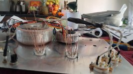
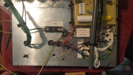
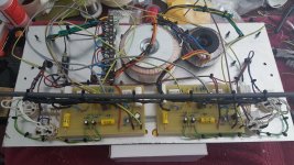
In that last photo you can see what I've done with the transformers. There are 2 x 240 - 115V transformers, one on top of the chassis and one underneath. Three of the four 115V secondaries are connected in series to give me 345VAC / 500VDC.
The smaller toroid is the 6V / 8A heater filament supply.
The smaller toroid is the 6V / 8A heater filament supply.
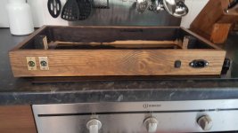
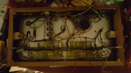
The wooden chassis is coming along.
I'm waiting for some components for the electronics so I'm finishing the wooden chassis.
I've installed the I/P sockets. I'm using XLR as all my Pass amplifiers use balanced connectors. I'm still undecided as to whether or not to use a balanced to unbalanced convertor or just use one side of the balanced input.
I'm waiting on a nice piece of brass to mount the O/P sockets.
Attachments
I'm using chassis mount tube sockets. Due to the interface between them and the PCB, the sockets will be 16mm away from the PCB. Does anyone have any advice on this ?
I'm aware that components such as grid stop resistors should be as close to the valve bases as possible.
On the EL34s the GS resistors are on the valve bases.
On the pre-amp tubes all the components are on the PCB.
I'm aware that components such as grid stop resistors should be as close to the valve bases as possible.
On the EL34s the GS resistors are on the valve bases.
On the pre-amp tubes all the components are on the PCB.
Moderators - could this thread be renamed to Maplin Millenium 4-20 ?
As this has now changed to a 4-20 build.
As this has now changed to a 4-20 build.
I've never built a valve amplifier before so I'm learning how labour intensive it is and how awkward the build becomes as the weight increases.
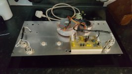
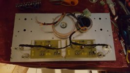
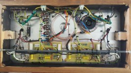
Today I have made some progress. The two PCBs are mounted in the chassis and the pre-power tube bases have been connected.
The heaters are all connected and I have heater power to all the tubes.
The 500V caps arrived and luckily they are slightly smaller than the 450V ones and actually fit on the PCB.
The wood under the PCBs is my version of PCB standoffs.
Attachments
Last edited:
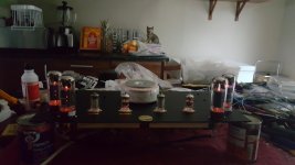
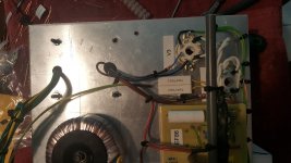
One last photo of todays efforts.
Tomorrow will be fun as I get to finish the project.
There's a lot of heater current flowing, some 8A, I hope my heater wiring will not produce any hum.
The heater transformer is dual 6V / 5A with each secondary feeding the heaters of the L and R channels separately.
Tomorrow will be fun as I get to finish the project.
There's a lot of heater current flowing, some 8A, I hope my heater wiring will not produce any hum.
The heater transformer is dual 6V / 5A with each secondary feeding the heaters of the L and R channels separately.
Attachments
Last edited:
Two Ns btw - Millennium.... 🙂Moderators - could this thread be renamed to Maplin Millenium 4-20 ?
As this has now changed to a 4-20 build.
I was puzzled by your earlier comment about a 47pF 600V capacitor. It is across a 100K resistor (R5) that is itself in series with a 270K (R6) from the filtered HT. As a consequence that capacitor can never see more than around 27% of the HT voltage, and only that much if the anode of the EF86 is pulled close to ground. Probably a 150 volt part would do, although 200 volts would allow a greater safety margin. Since that capacitor affects bandwidth I would stick with the polyester type if possible/ Ceramics generally have much poorer tolerances.
Two Ns btw - Millennium.... 🙂
I was puzzled by your earlier comment about a 47pF 600V capacitor. It is across a 100K resistor (R5) that is itself in series with a 270K (R6) from the filtered HT. As a consequence that capacitor can never see more than around 27% of the HT voltage, and only that much if the anode of the EF86 is pulled close to ground. Probably a 150 volt part would do, although 200 volts would allow a greater safety margin. Since that capacitor affects bandwidth I would stick with the polyester type if possible/ Ceramics generally have much poorer tolerances.
Unfortunately it is now too late to change the cap type.
Fair enough - it won't hurt just to see how it goes with what you already have in place.Unfortunately it is now too late to change the cap type.
They will get very hot after a period of running, so just watch out for any stray wires that run close by.I had to remove the chassis from the woodwork, but, thankfully that was easy enough to do.
Now I've got the 4 cathode resistors fitted.
Unfortunately it doesn't work
I've just finished the construction and have started testing it.
1. All heaters illuminate - Test passed.
2. B+ measures at 550VDC with no valves - Test passed.
3. B+ measures at 495VDC with all valves - Test passed.
12R 10W resistors are fitted as test loads.
LH amplifier seems OK.
RH amplifier is cooking the test load.
I've checked the phasing of the feedback, it is identical in both channels.
I've tried swapping the phase of the output transformer but that makes no difference.
Attachments
They will get very hot after a period of running, so just watch out for any stray wires that run close by.
Please see my earlier post. They are clear of any wires and are bonded t5o the aluminium chassis. At 7W rating they should be OK.
I haven't fitted the optional components R26, C16 nor RV1 and R27 so the input is open circuit into P1.
ie The grid of V1 is open circuit except for R1.
I can't see this being the problem as one of the channels is working OK.
ie The grid of V1 is open circuit except for R1.
I can't see this being the problem as one of the channels is working OK.
- Home
- Amplifiers
- Tubes / Valves
- ETI Hybrid EL34 amplifier