I've been planning some layouts with toroids, and they do take a lot of real estate compared with an EI transformer.
Where did you get your toroid covers from?
Have you considered putting the small toroid under the chassis? It could be mounted on the same spiggot as the top one. That'd buy you some space.
Where did you get your toroid covers from?
Have you considered putting the small toroid under the chassis? It could be mounted on the same spiggot as the top one. That'd buy you some space.
The transformer covers are available on EBay - "1PC 120*67mm Black Iron Round Amp Triode Transformer Protect Cover Enclosure Box"
Thanks for the pointer to the supplier, but, blimey!, $20, they are quite expensive!
I quite like the idea to have the toroid mounted vertically, with a third sunk through the top plate, and have a cover for going over the top two thirds, and keeping a compact layout. Aiming for a Quad II 'manhattan skyline' effect.
I quite like the idea to have the toroid mounted vertically, with a third sunk through the top plate, and have a cover for going over the top two thirds, and keeping a compact layout. Aiming for a Quad II 'manhattan skyline' effect.
I think I've mentioned it already.
This is not a project from the ground up.
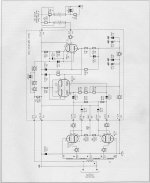
I came across the ETi article with the attached PCB and have just decided to give it a go.
The original article used hand wound transformers but there are no details.
I'm using a pair of B&W CM8s2 loudspeakers so 6K should be OK.
This is not a project from the ground up.
I came across the ETi article with the attached PCB and have just decided to give it a go.
The original article used hand wound transformers but there are no details.
I'm using a pair of B&W CM8s2 loudspeakers so 6K should be OK.
I you are really curious, an 8 ohm speaker can be connected to the 16 ohm tap to try how a 3k3 primary impedance would sound.I was hoping for some comments regarding the HAMMOND 1650H output transformers in this application.
Q1 and Q2 are shown as PNP on the schematic, but have NPN MPSA42 part numbers. Probably meant to be MPSA92 parts. You will also want relatively matched parts. With DC coupling, it will need thermal coupling between Q1 and Q2. Suggest changing to a MAT03 matched PNP transistors for the input and use MPSA92 transistors for a cascode stage (MAT03 only rated to 36V).
The (as shown) single stage Q1, Q2 collectors are going to have relatively large voltage swings for an input stage. Collector to base capacitance might be an issue. Usually a cascode stage gets used to fix that. With MAT03 matched inputs, it will need the MPSA92 above it (in collector paths) anyway for voltage rating.
Line voltage changes will change the -60V supply, affecting the -30V tube bias. A voltage regulator of some kind needed. Same for the screen grid supply. I suppose they might fortuitously track each other without regulation, but then the DC filtering time constants need to be matched.
Last edited:
Without V regulation, the screen V and -60V need to sag the same relative amount with plate current loading. There isn't any grid bias adjust shown. Class A?
I would keep Q1, Q2 ... away from tube heat also. Any change in their current gain will affect tube bias V. (well, the 1 meg tail R should hold that)
I would keep Q1, Q2 ... away from tube heat also. Any change in their current gain will affect tube bias V. (well, the 1 meg tail R should hold that)
Last edited:
I'm having a change of mind and am thinking about going for a Williamson 4-20 instead. I can just about manage it with the components that I've already got.
Since you were considering doing something different look at Michael Koster's Schadeode design as seen in post 12 in the following thread.
https://www.diyaudio.com/forums/tub...tial-feedback-se-amplifier-2.html#post2710121
He got an SE like harmonic structure with the 2nd harmonic dominating up to full output.
I built this design AC coupled without the cascode front end and tested it. I tested 6L6WXT+ and EL34 and got results similar to Michael's. With 1khz at 1 watt distortion was 0.1%, at 1% distortion it produced 7+ watts and 10+ watts at 3%. I also tried the same circuit with 6V6, 6CB5A, 6P20S, Chinese 6L6GC, 26LW6, 4D32 (16 watts). Except for output power I got similar results with all of these tubes.
Now, I am building a push pull test rig using this design. I wired an enhancement mode mosfet as split load PI and am using it as the input to the drivers. I have only tested it in SE but midband distortion went down to 0.08% at 1 watt.
Steve
That looks like a very slightly modified Mullard 5-20. Having built a pair myself last year, I can say that they are quite sensitive to oscillation depending on the performance of the output transformer. Large signal levels at low frequencies was always the trigger on mine. It also has way more gain than is necessary with modern sources.This is the version that I'm going for.
Two things I did on mine to improve it beyond faffing with the feedback to make it stable was replace ECC83/12AX7 with 6CG7 which improved the HF performance and reduced the gain. Removing the cathode bypass capacitor from V1 also helps with reducing the gain as the 5-20 is one very sensitive amp.
I also rewired the front end to use a 6BR7 instead of EF866 as they are superbly made and are 1/2 the price of the cheapest EF86's.
The project is under way
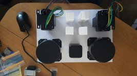
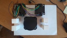
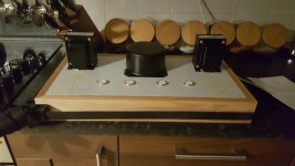
I've finally started on the metalwork.
The HTR transformer shares its mounting bolt with the HT transformer and is under the chassis.
As I started with the ETi design in mind I've had to go for an alternative HT approach.
The ETi design called for 230VAC for the B+, The 4-20 calls for 350VAC.
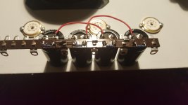
I didn't want to buy another mains transformer so I've used the original ETi transformer with a voltage multiplier. The 230V is actually 115V + 115V so paralleling these gives me 115V. That feeds a voltage quadrupler to give approx 450VDC.
Earlier someone did mention discharge resistors, you can see that each cap in the multiplier has a 210K resistor across it. Those red wires will be remade when it is fitted into the amplifier.
I've finally started on the metalwork.
The HTR transformer shares its mounting bolt with the HT transformer and is under the chassis.
As I started with the ETi design in mind I've had to go for an alternative HT approach.
The ETi design called for 230VAC for the B+, The 4-20 calls for 350VAC.
I didn't want to buy another mains transformer so I've used the original ETi transformer with a voltage multiplier. The 230V is actually 115V + 115V so paralleling these gives me 115V. That feeds a voltage quadrupler to give approx 450VDC.
Earlier someone did mention discharge resistors, you can see that each cap in the multiplier has a 210K resistor across it. Those red wires will be remade when it is fitted into the amplifier.
Attachments
That looks like a very slightly modified Mullard 5-20. Having built a pair myself last year, I can say that they are quite sensitive to oscillation depending on the performance of the output transformer. Large signal levels at low frequencies was always the trigger on mine. It also has way more gain than is necessary with modern sources.
Two things I did on mine to improve it beyond faffing with the feedback to make it stable was replace ECC83/12AX7 with 6CG7 which improved the HF performance and reduced the gain. Removing the cathode bypass capacitor from V1 also helps with reducing the gain as the 5-20 is one very sensitive amp.
I also rewired the front end to use a 6BR7 instead of EF866 as they are superbly made and are 1/2 the price of the cheapest EF86's.
I've got the valves as per the schematic for now but I will certainly note your comments if I have any issues.
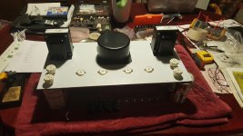
Ah! The Maplin Millennium 4-20. It's what I built in late 1994 - and I am still using it. 🙂This is the version that I'm going for.
I rolled my own power supply using a transformer that I had lying around.
Pictures here... https://www.diyaudio.com/forums/tubes-valves/71300-photo-gallery-501.html#post3463034
One thing to watch - the design was known to have occasional stability issues - Maplin did publish an amendment in March '95. I have the articles, so can scan if needed. I built mine using the Maplin PCBs as originally sold without making the later change. It's still like that.
- Home
- Amplifiers
- Tubes / Valves
- ETI Hybrid EL34 amplifier