The original Maplin parts are no longer available.
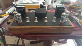
I'm using two toroidal transformers for the B+ and Htr supplies.
The OPTs are Hammond 1650H.
The PCBs are clones from the original artwork.
I'm using two toroidal transformers for the B+ and Htr supplies.
The OPTs are Hammond 1650H.
The PCBs are clones from the original artwork.
Understood - but I think it should still work OK. If anything, the Hammond 1650H will operate with far more headroom than the original transformers. Maplin did upgrade them at some point, but the 1650H that you have are still much larger.
I've had to lose one stage of the voltage multiplier. Off-load I was getting 700VDC.
With three stages I'm getting around 410VDC with a 70W load.
The danger with the multiplier is the excessive voltage while the vales aren't conducting.
With three stages I'm getting around 410VDC with a 70W load.
The danger with the multiplier is the excessive voltage while the vales aren't conducting.
I don't like the poor regulation of the multiplier so I'm changing the mains transformer to 350VAC as per the original spec.
OK. I couldn't find a 350V transformer so I've doubled up with 2 x 115V transformers. The two transformers are identical with 2 x 115V primaries and 2 x 115V secondaries.
Three of the secondaries in series gives me 345VAC - Close enough to the specified 350V.
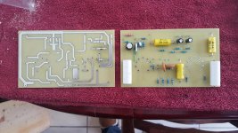
My main reservoir caps are made up of 220uF/450V in series, two pairs making 220uF/900V. There are 220K bleed resistors across each of the caps rescued from the original tripler construction.
My concern now is the off-load voltage.
Off-load the B+ measures at approx 550VDC. This is with the PCBs disconnected so only the bleed resistors as load.
On the main PCBs the decoupling caps are only rated at 450V. If you look at the schematic at #31 I am concerned about C2 and C7 (10uF/450V)
Are they going to be subjected to 550V until the valves start conducting and pulling the B+ down to approx 440V ?
Unfortunately I've had to resite the 6V transformer which ghas resulted in an extra hole in the chassis.
Three of the secondaries in series gives me 345VAC - Close enough to the specified 350V.
My main reservoir caps are made up of 220uF/450V in series, two pairs making 220uF/900V. There are 220K bleed resistors across each of the caps rescued from the original tripler construction.
My concern now is the off-load voltage.
Off-load the B+ measures at approx 550VDC. This is with the PCBs disconnected so only the bleed resistors as load.
On the main PCBs the decoupling caps are only rated at 450V. If you look at the schematic at #31 I am concerned about C2 and C7 (10uF/450V)
Are they going to be subjected to 550V until the valves start conducting and pulling the B+ down to approx 440V ?
Unfortunately I've had to resite the 6V transformer which ghas resulted in an extra hole in the chassis.
Attachments

Last edited:
Those capacitors will see over 500V if the output valves are not inserted or not conducting, and therefore at every start-up if you are using silicon diode HT rectification. My build uses valve rectification, so I avoid the start up issue, but I can seeing off 500V on the HT it if I unplug the output valves.
There are two solutions I can think of that are not two drastic... One is to source higher voltage capacitors, of course, but I accept that may not always be desirable. Another possibility would be some kind of soft-start for the HT. Assuming that you don't want to go to valve rectification, then other methods include timer circuits with relays to delay the HT (or at least slow it down), or negative temperature coefficient (NTC) thermistors which can potentially do the same thing by only passing a very small current until they are warmed up. There are many discussions on the HT delay topic on this forum and elsewhere.
There are two solutions I can think of that are not two drastic... One is to source higher voltage capacitors, of course, but I accept that may not always be desirable. Another possibility would be some kind of soft-start for the HT. Assuming that you don't want to go to valve rectification, then other methods include timer circuits with relays to delay the HT (or at least slow it down), or negative temperature coefficient (NTC) thermistors which can potentially do the same thing by only passing a very small current until they are warmed up. There are many discussions on the HT delay topic on this forum and elsewhere.
I am aware - I would not be surprised if the capacitors were a bit stressed under some conditions.
In answer to my own question. According to the datasheet, the Safety Voltage of the caps is 500V so they will be fine.
I've managed to locate some 10uF 500V caps anyway to be on the safe side.
I've managed to locate some 10uF 500V caps anyway to be on the safe side.
Last edited:
I'm predicting that the input valves will start to conduct quite quickly, add to that the charging current of the caps themselves and the B+ after R13 will probably stay comfortably below 500V.
The whole input circuit only needs to draw about 3mA.
What a shame there isn't a 450 zener diode.
The whole input circuit only needs to draw about 3mA.
What a shame there isn't a 450 zener diode.
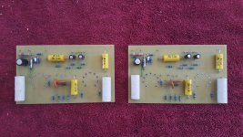
The PCBs are under construction
Ooohps, even after many proof reads of my clones of the Maplin PCBs I still found two errors after sending the design off for fabrication.
Never mind, the mistakes are easily corrected. One missing trace has been filled with the green wire that you can see. The other can be corrected with a link on one of the valve bases.
Unfortunately the positions for the two 10uF / 500V caps are a bit crowded. These can be either mounted on the other side of the board or just with slightly extended legs.
I'm struggling to find 47pF Polystyrene caps at 600V. I'm going to have to use ceramic caps.
Attachments
Retrospectively I have swapped the 470R 1W at the top left with the pins beneath it and uprated the resistor to 2W. This is unnecessary but just keeps the design layout as per the Maplin original.
Now I've got a major headache - any pointers would be appreciated.
My valve sockets are mounted from above the chassis with flying leads that need to pass through the PCB.
Any clues how to make the task of locating 18 wires easily ?
One thought is to make two sub-PCBs just to orientate the wires.
My valve sockets are mounted from above the chassis with flying leads that need to pass through the PCB.
Any clues how to make the task of locating 18 wires easily ?
One thought is to make two sub-PCBs just to orientate the wires.
I'm thinking that I can make some plastic rings that would mimick the valve bases so that the wire ends become a plug ready to match the holes in the PCB.
So you need to solder 18 stiff wires of slightly different lengths to your tube sockets, thread one after the other wire trough the PCB holes, solder and cut.
Btw, there are no tube sockets that would fit onto the PCB directly?
Best regards!
Btw, there are no tube sockets that would fit onto the PCB directly?
Best regards!
These sockets should do what you need:
B9a PCB mount sockets
You could do with some holes in the PCB for some standoffs which would anchor the board to the chassis.
B9a PCB mount sockets
You could do with some holes in the PCB for some standoffs which would anchor the board to the chassis.
So you need to solder 18 stiff wires of slightly different lengths to your tube sockets, thread one after the other wire trough the PCB holes, solder and cut.
Btw, there are no tube sockets that would fit onto the PCB directly?
Best regards!
This is exactly what I ended up doing in the end. It's still a pain in the a**e with two 9 pin sockets but it works.
- Home
- Amplifiers
- Tubes / Valves
- ETI Hybrid EL34 amplifier