D
Deleted member 148505
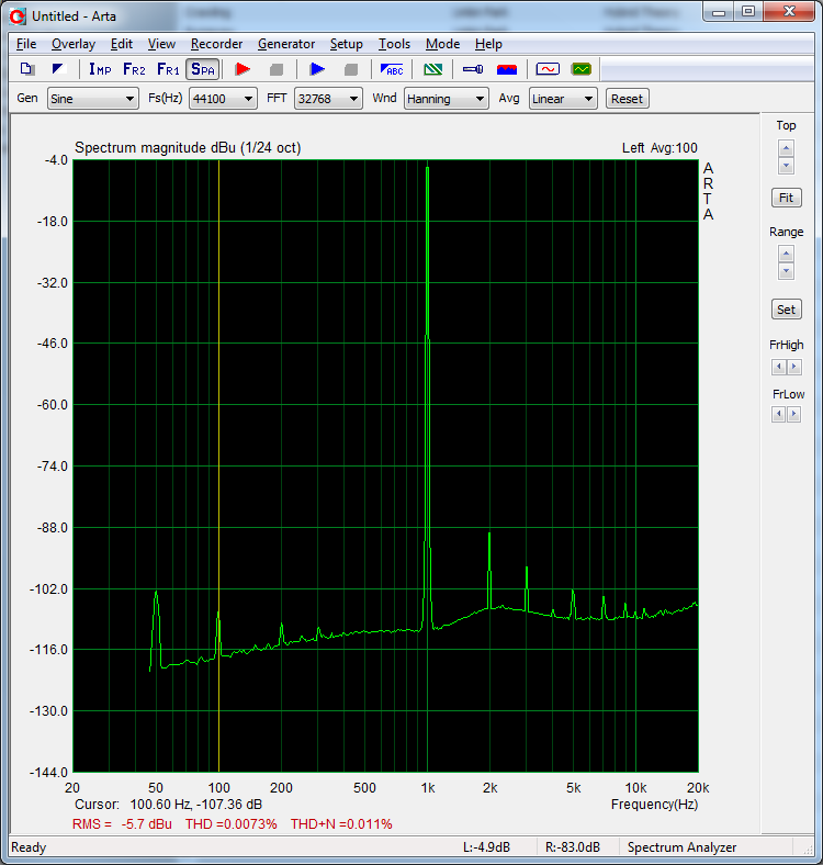
Take one torroid, 2 caps, 4 diodes and you get a better measurement than with a 400 dollar power supply.... I cheated a bit by using an iPhones battery operated signal generator, but when I used the iPhone with the labsupply I got 50-500 Hz noise, with the simple torroid that's less.
THD+N is around 0.012% at 1.6 Watt (3.9 Vac over 9.4 Ohm)
Update;
And adding 2*10 mF caps damped the 100 Hz peak by over 5 dB and 50 Hz by 4 dB. We are making progress. 4 days the output looked like http://www.diyaudio.com/forums/solid-state/212342-esp-p3a-layout-4.html#post3040762
Nice🙂
even-order harmonics are dominant
Even harmonics is unusual.
We usually see lots of third and hopefully lesser amounts of 5th and higher.
We usually see lots of third and hopefully lesser amounts of 5th and higher.
I did a THD+N test with the new layout. Performance is nearly identical. DC output is 2mV. There is some 50-100-150-200 Hz noise which I still want to suppress. For class AB, is adding more capacitance the only option?
http://www.diyaudio.com/forums/atta...5304d1338632396-esp-p3a-layout-added_caps.png
Is there a way of pushing the 50Hz peaks down? Better/different local decoupling? More PSU capacitance? Some sort of CRC topology PSU? Snubbered PSU (easiest to test, so I will use that today)
http://www.diyaudio.com/forums/atta...5304d1338632396-esp-p3a-layout-added_caps.png
Is there a way of pushing the 50Hz peaks down? Better/different local decoupling? More PSU capacitance? Some sort of CRC topology PSU? Snubbered PSU (easiest to test, so I will use that today)
Last edited:
I think it is in the PSU or PC. I cannot verify since I do not have better measurement equipment like a AudioPrecision
One way to go about it is the choice of transistors used in the LTP and as current source for the LTP. Very high beta LTP transistors will increase PSRR, as will high early voltage transistor used in the current source.
What types are you using at the moment ??
What types are you using at the moment ??
I use these transistors;
BC546
MJE15034
MJE15035
MJL4302
MJL4281
I added some capacitance and a 1R 100N PSU "Snubber" and the 100Hz dropped to -104 dB. I think the snubber is doing nothing, but the added capacitance helped a bit in the LF noise. Now I have 18mF (or 18000 uF) per rails for 1 channel.
Ow, and the LF measurement is caused by the amp/PSU. If I connect my signalgenerator/iPhone to the pc, there is no 50-100-150-200 Hz visible.
Last edited:
What is the measured hum on the output?
Measure with the input shorted, with the input open, with the input connected to your PC system.
Measure with the input shorted, with the input open, with the input connected to your PC system.
0 dBu is 0.77 Vrms
output amp -> 1:4 voltage divider -> PC
50 Hz -96 dBu therefore means; 0.000012277 Vrms on input of pc
0.000012277 Vrms * 4 = 0.049108 mV rms on amp output.
Connected to pc, AMP off;
50 Hz -113 dBu
100 Hz and up, masked by measurement noise.
Connected to pc, AMP on; Input open/floating;
50 Hz -75 dBu
100 Hz -102 dBu
150 Hz -102 dBu
200 Hz and up, -105dBu and lower
Connected to pc, AMP on; Input Shorted;
50 Hz -96 dBu
100 Hz -110 dBu
150 Hz -120 dBu
200 Hz and up, -113dBu and lower
Connected to pc, AMP on; Input connected to iPhone playing 1kHz sine;
50 Hz -96 dBu
100 Hz -100 dBu
150 Hz -115 dBu
200 Hz and up, -104 dBu and lower
In the previous post is a lot of info on LowFrequency energy content. However, I think you want to know the summed mVac on the output. It might seem bad due to the fact that I have a proper DMM.
Every amount of noise between 20Hz and 20kHz is measured and summed into 0.3 mVac. (shorted)
On the scope I cannot see a pattern, it is just flat/noisy.
Every amount of noise between 20Hz and 20kHz is measured and summed into 0.3 mVac. (shorted)
On the scope I cannot see a pattern, it is just flat/noisy.
SuperR, if you have a 2n5551c you should look at replacing the bc in the current source with this. For LTP BC546 is good, that is if its the BC546 C which has high beta. You can expect a handy couple of Extra Db in PSRR with just these 2 simple tweaks.
If you have D Self s book youll notice your output looks like an exact copy of his results when this problem area is not properly addressed.
If you have D Self s book youll notice your output looks like an exact copy of his results when this problem area is not properly addressed.
It is the BC546B, not the C....
I have Self's book, but I have not completely read it yet. Is there a page/chapter you can point me to?
I have Self's book, but I have not completely read it yet. Is there a page/chapter you can point me to?
The beta will be a bit on the lowish side with "B".
Im at work at the moment and my copy at home so I cant recall the exact chapter, but its right at the chapters end. You may find it looking at the term "PSRR" in the index pages.
Im at work at the moment and my copy at home so I cant recall the exact chapter, but its right at the chapters end. You may find it looking at the term "PSRR" in the index pages.
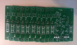
I just ordered my enclosure for the amp and have 5 channels of pcb+parts left/spare. If anyone is interested in this design, contact me.
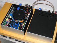
Afters months of PCB-layouting, prototyping, ordering parts and some metalwork, I am proudly presenting the result of this project!
The only thing it still needs is a proper testrun and a mains-fuse. (My electronics store is not opened today)
What is on the pictures?
2 enclosures. One for the Minidsp and one for the amplifier
Minidsp is used for the sub-sat filter
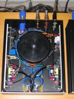
The amplifier is a very compact device at which I am proud since there is quite a lot of electronics in it. (230mm wide, 280 mm deep, 80mm high)
350VA 2*25VAC torroid
Rectifier on side panel
Elco-bank of 4 pieces 10.000uF 63Vdc
Two mono PCB's
A loudspreaker protection kit
Neutrik RCA entrance and mains inlet
Ebay terminals
The only thing it still needs is a proper testrun and a mains-fuse. (My electronics store is not opened today)
What is on the pictures?
2 enclosures. One for the Minidsp and one for the amplifier
Minidsp is used for the sub-sat filter
The amplifier is a very compact device at which I am proud since there is quite a lot of electronics in it. (230mm wide, 280 mm deep, 80mm high)
350VA 2*25VAC torroid
Rectifier on side panel
Elco-bank of 4 pieces 10.000uF 63Vdc
Two mono PCB's
A loudspreaker protection kit
Neutrik RCA entrance and mains inlet
Ebay terminals
Attachments

Very nice superR. I especially like your compact amp. That's a lot of electronics stuffed in there! 🙂 Where the enclosures stock, or your custom creations? Amps class A, AB perhaps?
Thank you very much. I really like the "end" result too. The enclosure is from Italy, ordered in The Netherlands. modushop.biz
The amp is a 90% copy of Elliots P3A and the pcb layout and schematic adjustments have been made by me in order to make the pcb fit vertically in the 80mm high enclosure.
The amp is a 90% copy of Elliots P3A and the pcb layout and schematic adjustments have been made by me in order to make the pcb fit vertically in the 80mm high enclosure.
- Status
- Not open for further replies.
- Home
- Amplifiers
- Solid State
- ESP P3A Layout