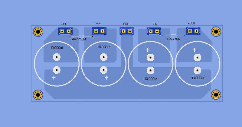
Don t know what woukd be better...i have 8 x 10.000uf so crc would be possible.
What benefits could i have from crc?
What benefits could i have from crc?
CRC is usually a little better for simpler amp designs. They usually don't have as good PSSR as some of the more complex designs.
You have enough caps to do dual CRC supplies. That would be the best route. The stereo separation/soundstage will be quite noticeably better with dual supplies, and you'll be less likely to have ground loop issues..
You have enough caps to do dual CRC supplies. That would be the best route. The stereo separation/soundstage will be quite noticeably better with dual supplies, and you'll be less likely to have ground loop issues..
CRC is usually a little better for simpler amp designs. They usually don't have as good PSSR as some of the more complex designs.
You have enough caps to do dual CRC supplies. That would be the best route. The stereo separation/soundstage will be quite noticeably better with dual supplies, and you'll be less likely to have ground loop issues..
Ok
Let's say 10k uf- 0.33 ohm -10k uf?
I don't use CRC supplies very often, so other's might have a better idea for the resistor value, but 0.33R sounds a little low.
I have used the Dx supply with success. Add an LC stage to it for super performance.
http://users.tpg.com.au/users/gerskine/
Here is my CRCLC:
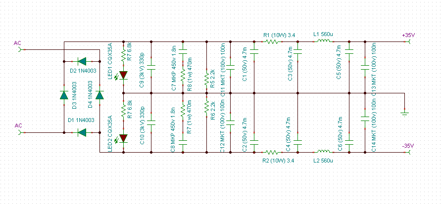
Point to point version:
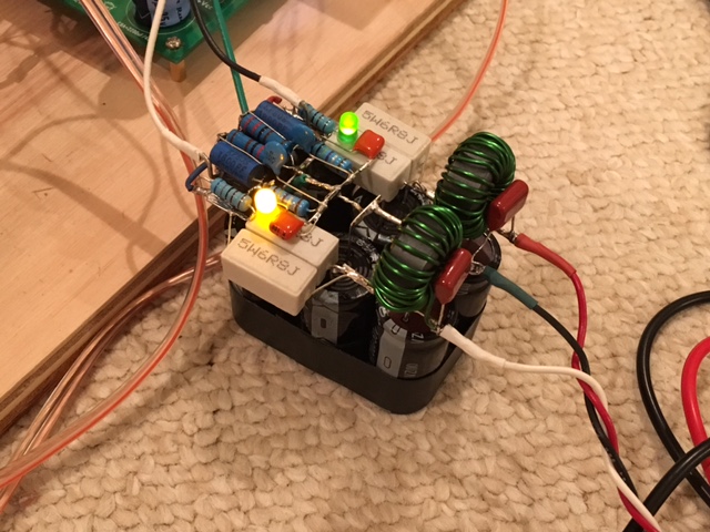
Note that I used 10A1 diodes and the inductor should be ideally a split core type designed to not saturate under heavy DC loads.
http://users.tpg.com.au/users/gerskine/
An externally hosted image should be here but it was not working when we last tested it.
Here is my CRCLC:
Point to point version:
Note that I used 10A1 diodes and the inductor should be ideally a split core type designed to not saturate under heavy DC loads.
Last edited:
very nice job!
i have little space in the case and for supply pcb (15cmx6cm) so i think I'll make a simple CRC...now let's find the value for the R
i have little space in the case and for supply pcb (15cmx6cm) so i think I'll make a simple CRC...now let's find the value for the R
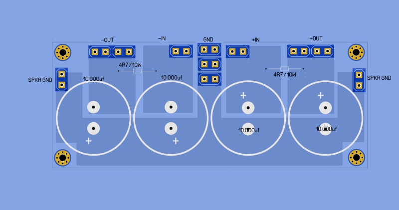
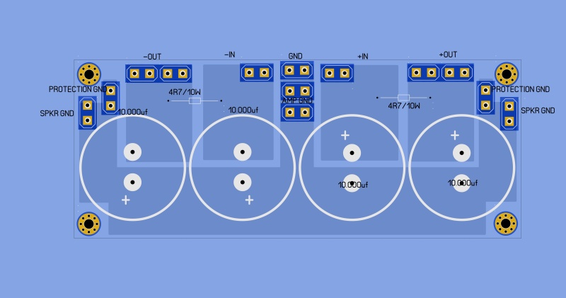
the 3 GND connections are:
-one from zero fo trafo
-each one to GND of P3a AMP;
I also added 2 GND connections direct to speaker minus from GND power supply...
Speaker protections will be powered directly from AC from the diode bridge, I have only an issue for the GND connection of these protections....would be better directly from GND of power supply or from GND of P3a amp?
It's best to ground everything at the supply. If you bring a ground return to the amp itself, you may inject any noise from what you are grounding into the amp ground.
Normally your ground connection from the transformer goes on one side of the supply, and all the other ground connections are made together on the other side. That bit of distance between the star ground and transformer ground helps.
You might want to add an LEDs with 4.7k on each rail to show circuit is alive and allows some bleed off; also 100nF 100V film caps to GND right on outputs is not a bad idea either to suppress noise. If you are taking rectifier bridge outputs directly to inputs, 330pF NP0/C0G ceramic or silver mica caps to 2W 4.7R to GND snubbers are good to suppress RF switch noise on diodes.
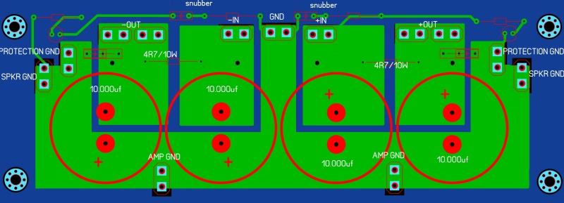
inserted snubber RC, output bypass caps, Led+R for eaach reail and moved the GND connectors....hope this will be good...what do you think about?
Member
Joined 2009
Paid Member
I wonder why somebody would even consider making the Chinese rich while Rodd Elliott is offering the proper PCBs for this project, as many as you want, NOW.
To boot, quite inexpensive.
And he *deserves* getting a couple dollars back, if any to help pay his server costs.
In theory DIY audio is against ripping Commercial products ... and then not even winks about profiting from a generous contributor?
I don´t get it.
This is DIY my friend - that's the whole point 🙂
I don't get the 4.7R/10W resistor. With 1A load you'll have 4.7V less at the amp supply. Why not a 1R resistor, not so good at decreasing the ripple but you'll only have 1V of drop.
I don't get the 4.7R/10W resistor. With 1A load you'll have 4.7V less at the amp supply. Why not a 1R resistor, not so good at decreasing the ripple but you'll only have 1V of drop.
ok, I was thinking also to get under 1 ohm (0.33-0.47). i don't think this amp is really noisy but I will see after powering it on
- Status
- Not open for further replies.
- Home
- Amplifiers
- Solid State
- ESP P3A Layout