
ok, I was thinking also to get under 1 ohm (0.33-0.47). i don't think this amp is really noisy but I will see after powering it on
Other possibility is to keep the 4.7R and use a high power diode across it. When the current is lower it gets the benefit of ripple reduction, when the amp needs lots of power the current goes through the diode and only drops about 0.6V.
So ripples > 0.6v will not have the benefit of the CRC filter with a diode?
At normal listening levels you'll have all the benefit of the CRC. When the amplifier needs more current for very loud music or a high current transient you will not have the benefit of the CRC but the power rails will not lower their voltage so the amp can reproduce these transients. Without the diode the amp will loose power when it needs it the most.
i saw many power supply for class AB amps. Many have a C(L/R)C filter that means a R of about 22/33ohm bypassed by an inductor wrapped on it.
In this case how does it work the CRC?
In this case how does it work the CRC?
P
In that case current flows mainly though the inductor with little resistance in the way. You have the benefit of ripple reduction and almost no voltage drop across the inductor. The resistor is not needed.
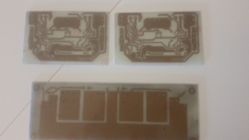
PS: your pcbs look awesome! I wish I could etch my boards as beatifully and professional looking as yours!
i saw many power supply for class AB amps. Many have a C(L/R)C filter that means a R of about 22/33ohm bypassed by an inductor wrapped on it.
In this case how does it work the CRC?
In that case current flows mainly though the inductor with little resistance in the way. You have the benefit of ripple reduction and almost no voltage drop across the inductor. The resistor is not needed.
PS: your pcbs look awesome! I wish I could etch my boards as beatifully and professional looking as yours!
so It can be conveniente use an inductor in place of the R...Do you know how many mH it should be? I can measure it.
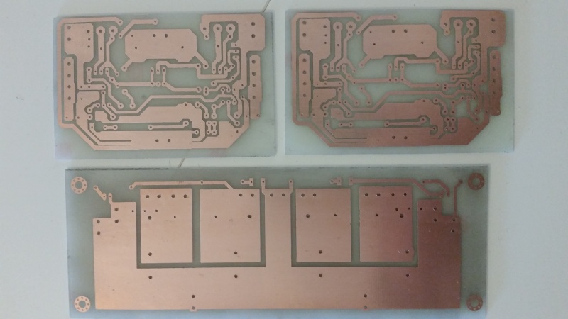
p.s. thanks a lot, I don't use a bromograph, only iron and Hcl. This is DIY my friend heheheh!!!!
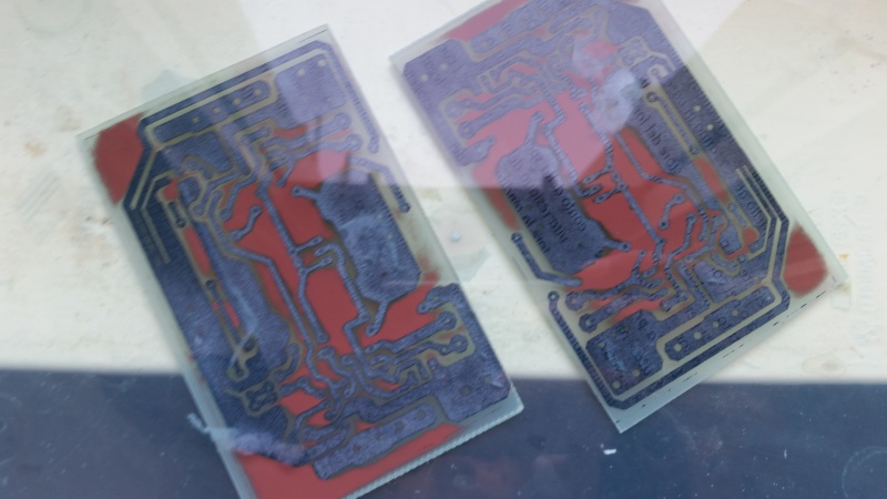
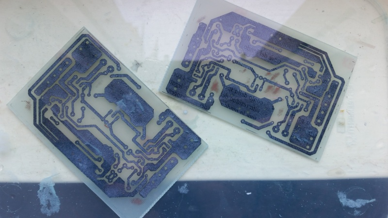
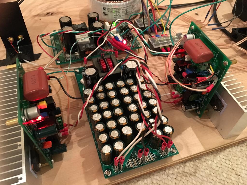
some pics of the realization of pcbs
p.s. thanks a lot, I don't use a bromograph, only iron and Hcl. This is DIY my friend heheheh!!!!
some pics of the realization of pcbs
The higher the better 😉
A good value would be 10mH, rated for the current demand of the amp. But that will be a very big inductor... no way you can put it on the pcb. Maybe something like 100uH?
A good value would be 10mH, rated for the current demand of the amp. But that will be a very big inductor... no way you can put it on the pcb. Maybe something like 100uH?
Last edited:
PCB ready for soldering!!!!
Beautiful work.
Btw, if you want to use an inductor, it needs to be a special split core one or an air core to avoid saturation (Coilcraft flat wire high current types are one option). Really, you should simulate the circuit to determine the size. But a good size that is effective is about 0.47mH and bigger its better. It is helpful to keep the resistor in this case - circa 33R to help dampen oscillations in the inductor. The inductors get big and if you want ripple suppresion, the 4.7R is better if you can't get an inductor that's big enough. The resistor is simple and cheap to test. Add the diode if you want but there is switching noise transients with a diode - which is why we used the snubbers in the first place.
Yes, keep the resistor for dampening eventual oscillations.
I use a 1R resistor and a MUR1520 across. The MUR shouldn't need a snubber.
The issue with higher value resistors is if the amps draws lets say 3A the rails will drop 14.1V with a 4.7 resistor and power goes way down.
I use a 1R resistor and a MUR1520 across. The MUR shouldn't need a snubber.
The issue with higher value resistors is if the amps draws lets say 3A the rails will drop 14.1V with a 4.7 resistor and power goes way down.
Member
Joined 2009
Paid Member
if you want to use an inductor, it needs to be a special split core one
Not really, when you think about current always flowing in loops then you get the possibility to use a different approach. See here: http://www.diyaudio.com/forums/solid-state/268846-tgm9-my-version-jlh-69-class-amplifier.html
Not really, when you think about current always flowing in loops then you get the possibility to use a different approach. See here: http://www.diyaudio.com/forums/solid-state/268846-tgm9-my-version-jlh-69-class-amplifier.html
Interesting but I am not sure where I see what you are saying. Can you please be more verbose?
CLC (or CRC, instead)for class A amp (JLH) has very sense because the current flowing remains the same. so you can dimension a CRC in order to have a (little of course) voltage drop but also a significant ripple reduction.
In class AB amp i'm not sure CRC is a good idea because of the variable current drawned by the amp. It also makes the internal impedance of the power supply growin up of a value =R of CRC.... the same is for CLC ....so probably I think should be correct to use a snubber network and a resistor on CRC of maximum 0,1 ohm
my 2 cents
first layout attempt
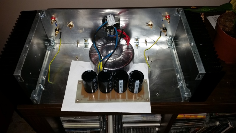
I recently built a P3A amplifier and the hum and noise is level is very low without any CRC or other type of extra filtering, I have 44000µF per rail, 20 X 2200µF 50V in parallel, I already had those capacitors laying around so I decided to use them all, not a scientific choice but it works really well.
Having several ohms between the capacitors basically means you have no use of the first capacitor when the amplifier needs lots of current during a transient, you will have less supply sag with the capacitors in parallel and the P3A does not seem to require any extra filtration effort anyway.
Having several ohms between the capacitors basically means you have no use of the first capacitor when the amplifier needs lots of current during a transient, you will have less supply sag with the capacitors in parallel and the P3A does not seem to require any extra filtration effort anyway.
Member
Joined 2009
Paid Member
Interesting but I am not sure where I see what you are saying. Can you please be more verbose?
With a common mode choke you have a choke in two rails (power and power-return) sharing a common core. Normally they are wired to reject common mode noise on an a.c. line without dc current. What I did was to wire the choke so that the dc current through one leg was opposite to the other leg thus cancelling out the dc in the core. The choke still acts to present a frequency dependent impedance to a.c. current flow, such as that from charging pulses of the rectifier.
With a common mode choke you have a choke in two rails (power and power-return) sharing a common core. Normally they are wired to reject common mode noise on an a.c. line without dc current. What I did was to wire the choke so that the dc current through one leg was opposite to the other leg thus cancelling out the dc in the core. The choke still acts to present a frequency dependent impedance to a.c. current flow, such as that from charging pulses of the rectifier.
Oh this is great news. I used a CMC in the usual way but was trying to use it for dual Inductors rather than common mode. Ok, so just reverse the connections on one side?
Here is mine:
Member
Joined 2009
Paid Member
Correct. You are effectively using it as a differential choke like that. You do know of course that chokes in power supplies cause a resonance due to the accompanying capacitors and you may want to consider if that's desirable, or if it needs to be damped with some series resistance.
- Status
- Not open for further replies.
- Home
- Amplifiers
- Solid State
- ESP P3A Layout