Well I must say my first experience has been a positive one. I ordered the terminals on the weekend and they arrived yesterday in an express post bag. The pins are a little thick for the holes in Rod's board - after a little work with a metal file they fit beautifully.
With any luck I'll have the project completed this weekend and then I can turn my attention to the preamp.
With any luck I'll have the project completed this weekend and then I can turn my attention to the preamp.
.......With any luck I'll have the project completed this weekend and then I can turn my attention to the preamp........
No ! First turn on the power amp and run it as it is and gives us feedback on how it sounds ! THEN you can start with the preamp .😉
Ha Ha Ha.... powering a P3A from a computer SMPS? it would be like a mercedes powered by 1000cc 50hp engine.Thanks for the post and hope you can post pictures of your build in progress.
I have Rod board and now accumulating parts .
Have you consider to power the amp with one of the smps power supply from Connexion ?
to the more knowledgeable here, can i power the P3A with dc 23 V+/- ? I have the F5 amp power supply to reuse ?
kp93300
power amps require an unregulated raw power supply with ample reservoir caps I think. that is my experience.
Not quite. Kp is referring to 2 single or a twin rail output SMPS unit(s) that can easily supply the necessary current without large caps. For that matter, PC supplies are now up to 500W rating so, if redesigned for twin rails output voltages, it could supply a number of P3as at the same time.Ha Ha Ha.... powering a P3A from a computer SMPS? it would be like a mercedes powered by 1000cc 50hp engine.
power amps require an unregulated raw power supply with ample reservoir caps I think. that is my experience.
Current delivery from SMPSs is not so dependent on the the massive caps needed for large amplifiers when driven by mains frequency AC. With around 400 kHz switching frequency, relatively small caps work quite well for audio on SMPS power. The safety factor is still a problem, though.
I don't see how a computer PSU could be made to work for high power amplifiers. They only put out serious current on the +5VDC and +12VDC lines, so even if you modified them to get +ve and -ve rails, the voltage is still too low.
What am I missing here?
Good quality computer power supplies are fairly expensive and the cost of two would be more than the cost of a transformer of equivalent combined rating. Purpose built SMPS for audio applications are expensive too.
What am I missing here?
Good quality computer power supplies are fairly expensive and the cost of two would be more than the cost of a transformer of equivalent combined rating. Purpose built SMPS for audio applications are expensive too.
The clue is the phrase "if redesigned for twin rails output voltages" and also in this ancient electrical proverb:
"The output voltage of a transformer is approximately equal to the input voltage multiplied by the square of the turns ratio"
Essentially, it means the PSU can be modded by reducing the number of secondary windings and altering the transformer turns ratio, so that instead of conventional PC supplies with +3.3V, +5V, -5V, +12V, -12V or a similar array of outputs, you redesign the transformer and regulator to have only +30V, -30V outputs or whatever you need, within the total maximum power rating of the supply . This is no different in principle, to making conventional transformers for different secondary output voltages.
This is actually a common and probably very dangerous practice in countries with no other access to affordable transformers or electronic components for high current, low voltage supplies like battery chargers, portable electronics, DC drive motors, tools etc. Even Silicon Chip magazine featured a very popular 12V project like this, about 10 years ago.
Again, I don't suggest anyone actually do this. The example is only for illustration and in explanation of existing amps that indeed use SMPS. There's a big difference though, between supplies that are sealed within a consumer device case and safely grounded, to those off-line types that are open, free standing and left that way for fiddling with.
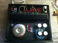
Well I finished the wiring over the weekend, testing everything as I went. I'm pleased to report that everything worked 100% first time.
Quiescent current is set to 75mA, in accordance with Rod's instructions. The heatsink is barely warm to the touch when the amp has been idling for a couple hours. I'd say its only a couple degrees over ambient - if that.
Here's a few grainy photos I took before putting the lid on. I'll take some better ones soon and update this thread.
Attachments
Thanks Ian and everyone else who contributed to this build... much appreciated.
I should also credit martinbls whose photo in the build pictures thread gave me the idea for the layout:
http://www.diyaudio.com/forums/soli...ur-solid-state-pics-here-146.html#post2237192
I should also credit martinbls whose photo in the build pictures thread gave me the idea for the layout:
http://www.diyaudio.com/forums/soli...ur-solid-state-pics-here-146.html#post2237192
Great that it all works without drama, Ranchu. Enjoy! 🙂
With all that sinking, you won't have heating or stress problems but take care to trim the excess of output leads, power leads etc. Route power well away from input/output leads and twist the DC Power leads for each amplifier tightly together back to the power supply to limit spurious noise or possible instability. Obviously, for very short runs, there's not much point trying.
'Just standard design procedure, really. Don't forget to give us a listening check!
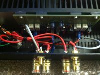
I've tried to separate the high voltage, DC power, low level signal and speaker wiring as best I can. A few points:
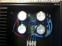
- I have +35VDC, -35VDC and ground lines running from the amp module to the PS board.
- I have a separate speaker ground wire from the terminal back to the cap bank "ground plane" also.
- There's a 25VAC wire taken off one of the transformer secondaries that runs alongside the DC wiring into the loudspeaker protection circuit on the top right of the board.
Which wires would you suggest pairing/twisting?
There's actually not a lot of space between the amplifier board and the back of the case! Nonetheless I am going to try and shorten/reroute the wiring to improve separation.
Ian, I've only had the chance to listen for an hour or so. I'm no audiophile and find it difficult to express in words the difference between audio components. Suffice to say, from my test I am impressed with this amp. Compared with my Marantz AV receiver, I would say stereo imaging is improved; instrument placement is distinct. Lower frequencies (e.g. bass guitars, kick drums) are pronounced and crystal clear.
I tested it using high quality FLAC material output from a DAC directly to the P3A's inputs and the software volume control set about 25%. Connecting a CD player directly to the amp inputs resulted in far too high a volume (I need an attenuator or preamp before I can test this source).
Perhaps the most interesting observation is that the outputs are dead silent even with the volume set near maximum. At the same settings there was always a slight hum from the speakers, which I assumed was the source. Even with my ears up to the speaker cone I can't detect even the faintest hiss.
I suspect the amp as built lacks the power to drive these loudspeakers to very high volumes. With the software volume control set to levels somewhat higher than normal listening levels the quality deteriorates, particularly on material with a lot of bass. The outputs don't clip like some amplifiers I've heard when overdriven; rather the sound slightly muddies.
All in all the sound quality is excellent and exceeds my expectations.
Now I'm starting to think about what to build next after I've finished my preamp project? 🙂
As posted, the DC power rails (that's +/- 35V rails from the power suply to the amplier.....Which wires would you suggest pairing/twisting?......
The rest, I think you will understand well enough, realizing that low current, smooth 50Hz AC loads are much less of a problem. It's about the power being switched and how quickly, all the way back to the mains socket. Big offenders also being the rectifier, smoothing caps and their leads which you have already taken care of.
By way of explanation; In a class AB amp, the +/- rails alternately supply positive and negative halves of the output waveform, so they switch on and off sharply at the crossover (0V) potential and this action causes a pulse to flow alternately from each rail, even with nice, smooth sinewave tones. The pulse generates significant electromagnatic radiation (EMR) from the leads which is picked up by the amp and any other nearby sensitive circuitry.
Twisting the leads together effectively reduces the EM field strength which is a reduction in unwanted distortion. This is not restricted to just power leads - it's critical to PCB design layout that output stage and feedback is arranged for minimal interference by the placement of traces and ground routing but this is for the P3a PCB design thread guys to worry about, because it can easily make the difference between high-end and so-so sound quality.
I'm sure Rod Elliott has covered this in his articles and just in the last week or so, Bob Cordell discussed the lead twisting matter in one the threads he frequents -probably the book thread. Maybe one of the Randy Slone, Douglas Self or Bob Cordell books would be a good read and help you make your own mind on this stuff, even if you don't find technical stuff easy going. 😉
BTW -nice review, honest and good stuff!
I like your layout.
Amplifiers right next to inputs and outputs.
Heatsink increasing the space between amplifier and PSU and giving a form of grounded screen in between as well.
Twist Every Flow and Return, both AC and DC, low level signals and mains cables.
Amplifiers right next to inputs and outputs.
Heatsink increasing the space between amplifier and PSU and giving a form of grounded screen in between as well.
Twist Every Flow and Return, both AC and DC, low level signals and mains cables.
Hi
How do i match the Bc 546.
1) I matched the hfe for Q1, Q2 and Q3 so that both channels are the same values or do i match it for each channel?
2) Do i need to match Q9 to Q1,2,3? Or macth Q9 for both channels?
3) Can i use BC550 at Q9 and use Bc 546 for Q1 to Q3?
The schematic is here 60-80W Power Amplifier
thanks
kp93300
Hi kp93300
None of the transistors need to be matched. I don't see why you would ever need to match across channels.
Cheers
None of the transistors need to be matched. I don't see why you would ever need to match across channels.
Cheers
Hi Ranchu 32
thanks.
I consider matching because of sarkis comments in the other thread.
cheers
kp93300
thanks.
I consider matching because of sarkis comments in the other thread.
cheers
kp93300
OK - I haven't read Sarkis' comments in the other thread. For what it's worth, Rod Elliott doesn't state that any of the transistors need to be matched, and my subjective impression of the sound quality with unmatched parts is very good.
If one has unlimited budget to buy much more transistors than needed to build amp, and unlimited time to match them, and wants the best possible specs, than it's OK to match transistors. But it is not really necessary.
Ivan, do you think that simply matching the input transistors to each other is a good compromise @ minimal extra cost? That is the BC546, Q1, Q2.If one has unlimited budget...
One can learn some useful things by making a small circuit to measure hfe with a simple multimeter, even if you can't achieve a perfect match.
In any case, I am sure there is no point in matching between channels, I don't see how you could get any benefit from that in this case. I know Sakis is a perfectionnist, and I learned a lot from his posts, but I don't remember him recommending that 😱 (?)
- Status
- Not open for further replies.
- Home
- Amplifiers
- Solid State
- ESP P3A component recommendations