An external clock sounds like a good project idea. I can try it with both the currently very good and currently poor jitter interfaces and compare the JTest results to the internal clocks.
Which logic family do you think is best? (Including for the dividers and driving the 75 Ohm outputs?)
Which logic family do you think is best? (Including for the dividers and driving the 75 Ohm outputs?)
Normally 50-ohms for clocks. 75-ohm is more common for SPDIF and video.
J-test is useless unless you have spurs. No good information about close-in phase noise performance.
If you need and use 45/49MHz clocks, why dividers? Or do some of the chips need 22/24MHz, and others 45/49MHz?
J-test is useless unless you have spurs. No good information about close-in phase noise performance.
If you need and use 45/49MHz clocks, why dividers? Or do some of the chips need 22/24MHz, and others 45/49MHz?
J-test is useless unless you have spurs. No good information about close-in phase noise performance.
Great, that's an audio red herring, anyway.
You and your posse still own everybody evidence that this "close-in phase noise" audio red herring has anything to do with SQ.
I have not used external clocks (only the internal) on these interfaces so take this with a grain of salt: The master clocks that are sold to be used with these interfaces have 1x/2x/4x and 44.1/48 switches which you set depending on what rate you are recording at. In other words it appears that the interfaces do not divide down the word clock in the same manner that they do when you are using the internal clocks. If you use the internal clock then the software & drivers handle the division plus the switching between the two oscillators.
If you get one of the upgrade clock boards installed then it is just 45.158 & 49.152 MHz and then the digital board/FPGA handles necessary division.
The manual also references 75 Ohms:
If you get one of the upgrade clock boards installed then it is just 45.158 & 49.152 MHz and then the digital board/FPGA handles necessary division.
The manual also references 75 Ohms:
003 and 003 Rack provide Word Clock In and Out connectors on the back panel that let you synchronize, or “clock” Pro Tools LE and the 003 or 003 Rack to industry standard Word clock. Word clock is used to synchronize a wide range of devices such as non-linear video systems and other types of equipment typically found in professional audio facilities.
With both Word clock input and output, your Pro Tools LE system can act as Word clock “slave” or “master.” To connect 003 or 003 Rack to Word clock:Using high-quality, 75 Ohm BNC cables (not included), connect the 003 or 003 Rack Word Clock In and Out connectors to the appropriate ports on the other Word clock-capable devices in your studio.
Okay. Word Clock is an old studio standard from the days of trying sync everything together with PLLs. Don't know if it still has much practical use today. IIRC, Box Katz argued in Mastering Audio that its not good nor needed for mastering.
OTOH, AES (professional version of SPDIF, IIRC usually balanced ~110 ohm) is still used in professional studios. ASRC is the usual way AES is reclocked in studio use. Ends up sounding better than trying to sync PLLs with Word Clock.
EDIT: For clock division I might try a carefully implemented version of ICS542. Supposed to be capable of very low phase noise with proper implementation. Some application hints from the datasheet:
"3) An optimum layout is one with all components on the same side of the board, minimizing vias through other signal layers (the ferrite bead and bulk decoupling capacitor can be mounted on the back). Other signal traces should be routed away from the ICS542. This includes signal traces just underneath the device, or on layers adjacent to the ground plane layer used by the device."
I agree with that (maybe except for the ferrite bead inclusion) even though I don't have 'proof' for certain people that the advice helps.
Last edited:
So perhaps I should not try building an external word clock? Perhaps I should switch back to the idea of making a carefully designed 45.158 & 49.152 MHz oscillator "upgrade" board with a very clean power supply, good layout and a decent buffer?
(Like the images in post #7119.)
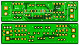
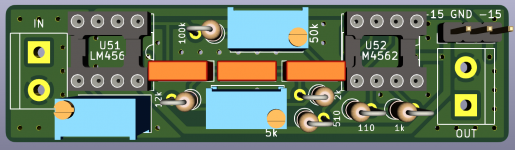
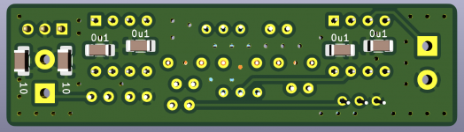
Another example (for a different interface) is shown here: The ο1 precision master clock
(Like the images in post #7119.)
Another example (for a different interface) is shown here: The ο1 precision master clock
I agree that providing the internal clock signals needed rather than Work Clock would probably be the best bet for good results.
The clock board you linked to is one that I have tried. IMHO it is marginal in certain respects. For example, both clocks do not always run, its only 2-layer, the voltage regulation is not great compared with other solutions, decoupling is not optimal. Also, it has no divider function. If you want a good clock board I'm afraid you or someone else should probably design one. I don't know of an off-the-shelf one I would want to use, tried a number of different clock and USB board designs before saying that.
The clock board you linked to is one that I have tried. IMHO it is marginal in certain respects. For example, both clocks do not always run, its only 2-layer, the voltage regulation is not great compared with other solutions, decoupling is not optimal. Also, it has no divider function. If you want a good clock board I'm afraid you or someone else should probably design one. I don't know of an off-the-shelf one I would want to use, tried a number of different clock and USB board designs before saying that.
What people have done is monitor the I2C bus when the dac boots up and or when inputs are switched by moving jumpers. Capturing that data gave some clues to using the dac chip. However, now that ESS has opened up the datasheets we are free to talk about how to program the dac chip to do whatever. No longer any need to watch the dac board MCU do it.
I'm finally getting round to replacing the MCU for my 9038Q2M and pleased to see that this can now be discussed openly. Is there now a new approach to go about this. If this has been covered already let me know and ill go back and read through some more.
I have I2S isolator fitted, Pi is in there already as a network source on SSH, Arduinos also to hand in drawer. logic analyser at the ready.
can the BuffaloDAC/ES9028.h at master * possum64/BuffaloDAC * GitHub (thanks bimo) code be used as is (individual micro controller set up aside)?
eightdigitword ,
One forum user has already adapted some of Dimdim's ES9038PRO code to ES9038Q2M. Maybe he can speak to that.
Other than that maybe I can help with register programming info. My question for you would be what do you know so far about interfacing Arduino, I2C bus, and dac register programming (please give me a clue as to where to start)? Thanks.
Raspberry Pi is a very powerful tool for I2C development.
Code can be developed in C and then ported back to Arduino (or other others - Pi Pico etc) with a couple of changes to the I/O functions.
I am currently using TeamViewer under Windows to control a PI connected to four 9038 DACs.
Debug from anywhere.
Code can be developed in C and then ported back to Arduino (or other others - Pi Pico etc) with a couple of changes to the I/O functions.
I am currently using TeamViewer under Windows to control a PI connected to four 9038 DACs.
Debug from anywhere.
Last edited:
...can the BuffaloDAC/ES9028.h at master * possum64/BuffaloDAC * GitHub (thanks bimo) code be used as is (individual micro controller set up aside)?
Don't know that anyone has read through it to see. Register map is somewhat different between ES9038PRO and ES9038Q2M, so some changes would be presumably be needed.
If there is a particular thing you want to program ES9038Q2M to do, we could always talk about the registers and bits involved for doing that.
This should give you a start -
GitHub - VinnyLorrin/ES9038Q2M-Linux_Driver
and to a lesser extent
GitHub - audiophonics/I-Sabre_9038Q2M: New Audiophonics I-sabre 9038Q2M driver
GitHub - VinnyLorrin/ES9038Q2M-Linux_Driver
and to a lesser extent
GitHub - audiophonics/I-Sabre_9038Q2M: New Audiophonics I-sabre 9038Q2M driver
Raspberry Pi is a very powerful tool for I2C development.
Code can be developed in C and then ported back to Arduino (or other others - Pi Pico etc) with a couple of changes to the I/O functions.
I am currently using TeamViewer under Windows to control a PI connected to four 9038 DACs.
Debug from anywhere.
That much is clear.
i'm yet to get my feet wet with rpi; your toolset sounds very interesting, as it is exactly my use case, as well as prospective measurement abilities. I plan arduino zero or similar embedded in dac cluster and pi at the centre and a calibrated USB mic and my friend is keen on Camilla for DSP. Do you have a page where you explore your project in more detail? I am at this stage looking to embed 1 or 2 RPi 4 compute modules, on a purpose built base board, with master clock. Thats one of the threads i'm following anyway, along with hardware DSP on an SoC/FPGA in the most hardware centric end.
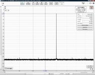
I was wondering if I could get some help interpreting the attached JTest results.
The first is my older result of the ES9038Q2M DAC measured by my E-MU 1820 which has a PCM1804 ADC.
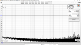
The second is from my Digidesign 003 rack loop back which is CS5361 ADC reading the CS4392 DAC. [After I soldered 0.1uF and 1uF MLCC directly to the clock oscillator NXP 74HCU04D pins, plus OS-CON caps across the surface mount ceramic caps for each of the logic gates used to distribute the clocks to the 8 ADC and 8 DAC channels.]
[I kept the same FFT and display settings so that the new measurement could be compared to the old ES9038Q2M & E-MU 1820 measurement.]
The last image is the Digidesign again but before I improved the bypassing of the clock oscillator and clock distribution circuits. I think the close in jitter related spurs have improved by about 11 dB.
How good are these results? Perhaps I do not need to replace the clock now? (I am thinking of moving on to the next upgrades and calling the JTest "good enough".)
The first is my older result of the ES9038Q2M DAC measured by my E-MU 1820 which has a PCM1804 ADC.
The second is from my Digidesign 003 rack loop back which is CS5361 ADC reading the CS4392 DAC. [After I soldered 0.1uF and 1uF MLCC directly to the clock oscillator NXP 74HCU04D pins, plus OS-CON caps across the surface mount ceramic caps for each of the logic gates used to distribute the clocks to the 8 ADC and 8 DAC channels.]
[I kept the same FFT and display settings so that the new measurement could be compared to the old ES9038Q2M & E-MU 1820 measurement.]
The last image is the Digidesign again but before I improved the bypassing of the clock oscillator and clock distribution circuits. I think the close in jitter related spurs have improved by about 11 dB.
How good are these results? Perhaps I do not need to replace the clock now? (I am thinking of moving on to the next upgrades and calling the JTest "good enough".)
Attachments

Ah, sorry for the confusion. I mean figuratively, one of the threads of (my) interest; ie. direction of enquiry, not an actual forum thread.
Kozard,
Looks like you got some decent improvement by relatively simple means. Taking the spurs way, way down would likely be more trouble than its worth for that old Digidesign unit. Most likely it still has other audible issues that might benefit from fixing first, assuming of course it might sometimes be used for purposes other than just measurement.
Looks like you got some decent improvement by relatively simple means. Taking the spurs way, way down would likely be more trouble than its worth for that old Digidesign unit. Most likely it still has other audible issues that might benefit from fixing first, assuming of course it might sometimes be used for purposes other than just measurement.
Kozard,
Looks like you got some decent improvement by relatively simple means. Taking the spurs way, way down would likely be more trouble than its worth for that old Digidesign unit. Most likely it still has other audible issues that might benefit from fixing first, assuming of course it might sometimes be used for purposes other than just measurement.
The main purpose of the Digidesign and E-MU are not measurement. It is just that when I started working on the ES9038Q2M the E-MU was the most suitable measurement tool I had.
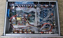
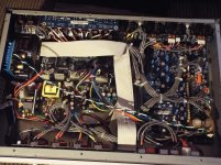
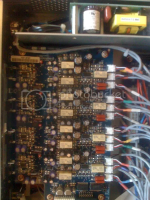
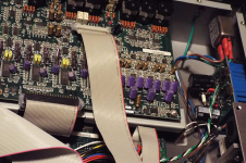
There are big opportunities for sound improvement from the reports of many others who had their units upgraded with OPA4134 op-amps (instead of TL074) and better capacitors. I have photos of a number of generations of upgrades and in earlier units OS-CON and Nichicon FG were the main upgrades. In more recent units it appears that Vishay (for digital) and Nichicon FW (for audio) are the preferred upgrades. I am going to try Panasonic FM (audio) and Panasonic SEPC (OS-CON, for digital). I don't know which op-amps were used to upgrade all the dozens of NE5532. (Guess is OPA2134.)
In the attached photos the purple are the OSCON, the blue are Vishay and the gold are the Nichicon upgraded capacitors.
At the end of those upgrades I will either leave the clocks as they are now or investigate an ultra low noise LDO there, etc. The other main upgrades people did were upgraded analog power supplies for the op-amps and the replacement master clock boards.
Attachments
Last edited:
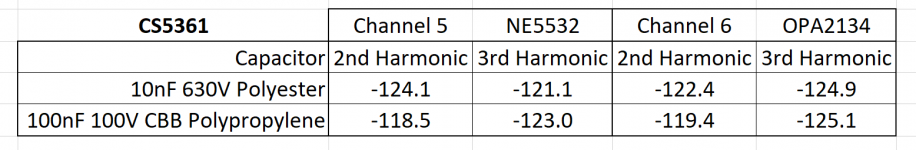
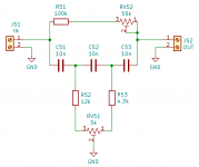
I have built and tested three of the passive 1kHz Hall Notch Filters. Before I build the active notch filter I need to understand why my measurements vary up to 6 dB between the filters.
For example, the 2nd harmonic measures better on the version that uses 630V rated green polyester 10nF capacitors. The next version was intended to be better (with lower insertion loss) with 100nF red CBB polypropylene capacitors and 10x smaller resistors.
I am using 1% metal film resistors and 3296 trimmers. I have also measured the notch three times before the DAC measurement and three times after and the overlay is exactly on top of each other. (So reasonably stable.)
Originally I thought that 630V rated polyester might have a sufficiently small voltage across them (in this application) to not produce measurable distortion. Perhaps this is a mistake and I should not use them.
I next used 100nF red CBB polypropylene capacitors so that I could reduce the resistors 10x and reduce insertion loss. Also I thought that the polypropylene might have lower distortion even though these are only rated 100V. However now I measure worse 2nd harmonic. (With polypropylene and significantly less insertion loss from 10x smaller resistors.)
For next steps perhaps I should try?
- C0G/NP0? (Caps are a bit large for C0G/NP0.)
- WIMA FKP 3 Polypropylene (PP) Film and Foil Capacitors for Pulse Applications.
- Higher quality resistors? Most of my 1% metal film resistor assortments are steel lead. At what distortion levels are this type a problem?
Attachments

Last edited:
Added information: I just checked with a magnet and every component is magnetic. The yellow box 100V polypropylene caps (the first of the three filters), the red CBB 100V polypropylene caps, the green 630V polyester caps, and the 1% leaded metal film resistors.
I even found that the 1% 1206 metal film resistors are magnetic. (I was hoping that they were not magnetic as a possible alternative.)
Is this a problem at these distortion levels?
I even found that the 1% 1206 metal film resistors are magnetic. (I was hoping that they were not magnetic as a possible alternative.)
Is this a problem at these distortion levels?
Last edited:
- Home
- Source & Line
- Digital Line Level
- ES9038Q2M Board