Just to clarify - changing V1 from 3 cubic feet, driver diaphragm diameter from 15 inches, or Cms from 4.00E-04 metres/newton, will change the resulting 'cubic inches per cubic foot' figure. The figure will also change slightly depending on the chosen values for the two pressures differing by 1 inch of mercury. For example, 29.5 in Hg and 30.5 in Hg will give a slightly different result to 29.0 in Hg and 30.0 in Hg.
Precise of David to highlight variables that influence air expansion. But size of driver assembly, compliance, size of box, and relative location on the mercury scale can't make too much difference, I would say.
So wouldn't the rough estimate of one "inch" of mercury resulting in 50 cu inches of expansion for every cu foot enclosed in a sealed box seem quite good enough for the kind of soft guess appropriate to purposes here?
B.
Doesn't getting that particular parameter representative have a very large influence on sag?
Ideally, the values of both Mmd and Cms need to be accurate.
Some woofers are 200 grams and more.
Rockford Fosgate Power T3S1-19 superwoofer:
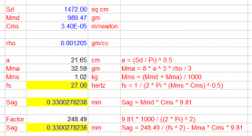
Mmd = 989.47 grams
Cms = 3.40E-05 metres/newton
Sag = 989.47 * 3.40E-05 * 9.80665 = 0.33 millimetres (Xmax = 34 mm)
Alternate formula:
fs = 27 hertz
Sag = 248.49 / (fs ^ 2) = 248.49 / (27 ^ 2) = 0.34 millimetres
So wouldn't the rough estimate of one "inch" of mercury resulting in 50 cu inches of expansion for every cu foot enclosed in a sealed box seem quite good enough for the kind of soft guess appropriate to purposes here?
It depends on how much "softness" you are prepared to accept 🙂.
To illustrate, taking the example given in Post #72 where the displacement is calculated to be 0.83 inches, if the diameter of the driver diaphragm is reduced from 15 inches to 10 inches, the displacement increases to 1.21 inches.
The "50 cubic inches per cubic foot" rule of thumb would give the result as 1.91 inches, a 58 percent inaccuracy...
Ideally, the values of both Mmd and Cms need to be accurate.
Rockford Fosgate Power T3S1-19 superwoofer:
Mmd = 989.47 grams
Cms = 3.40E-05 metres/newton
Sag = 989.47 * 3.40E-05 * 9.80665 = 0.33 millimetres (Xmax = 34 mm
Right, the suspension must compensate with added stiffness when the cone assembly weight is gross.
In both cases (20 gr and 989 gr) the sag is small but a lot bigger for the monster high-power driver (.09 mm versus .34 mm).
Some folks unfamiliar with SI will be interested to learn that the Fosgate super woofer cone assembly weighs 2.2 lbs.... which seems awfully heavy to waft about to me as you can compare the contrasting world-views of the Lotus and the Corvette
B.
Thanks once again.It depends on how much "softness" you are prepared to accept 🙂.
To illustrate, taking the example given in Post #72 where the displacement is calculated to be 0.83 inches, if the diameter of the driver diaphragm is reduced from 15 inches to 10 inches, the displacement increases to 1.21 inches.
The "50 cubic inches per cubic foot" rule of thumb would give the result as 1.91 inches, a 58 percent inaccuracy...
Yes for sure, a smaller cone will budge a whole lot more. But I don't understand why the cu feet of enclosed air behaves differently aside from a suspension stiffness trim?
BTW, "58%" error is more than accurate enough for a calculation that (1) has been pure guesswork around here before you provided it and (2) that has no detailed impact on guessing how big a pin hole should be.
B.
But I don't understand why the cu feet of enclosed air behaves differently aside from a suspension stiffness trim?
As indicated in Post #78, the 'cubic inches per cubic foot' figure will vary appreciably depending upon the values of Sd and Cms, and vary slightly depending on the starting pressure P1.
Disregarding Cms for the moment…
We know from Boyle's Law that P1 * V1 = P2 * V2 which can be rearranged as follows:
V1 / V2 = P2 / P1
If the pressure increases by 1 unit, the general formula becomes:
V1 / V2 = (P1 + 1) / P1
If the starting pressure is 29 inches of mercury V1 / V2 = (29 + 1) / 29 = 103.45%
If the starting pressure is 30 inches of mercury V1 / V2 = (30 + 1) / 30 = 103.33%
Therefore, if Cms is disregarded and the starting pressure is in the normal barometric range, then the approximate 3% or '50 cubic inches per cubic foot' rule can be applied for a pressure increase of 1 inch of mercury.
When Cms is included, things get more complicated…
Starting with the formula given in Post #72:
P2 = P1 * V1 / (V1 - X * Sd) + X / (Cms * Sd)
And knowing that:
P2 = P1 + 1
V2 = V1 - X * Sd
Substituting and rearranging:
P1 + 1 = P1 * V1 / V2 + X / (Cms * Sd)
P1 * V1 / V2 = P1 + 1 - X / (Cms * Sd)
V1 / V2 = [(P1 + 1) / P1] - [X / (Cms * Sd * P1)]
This new expression for V1 / V2 has a similar form to the earlier one, but with a negative [X / (Cms * Sd * P1)] term now added. The V1 / V2 ratio or percentage will therefore now vary from the nominal 103% value, depending on the values chosen for Cms and Sd, and to a lesser extent, P1.
has no detailed impact on guessing how big a pin hole should be.
The pin hole can be a small as you like, given that the diameter of an air molecule is 4 x 10⁻⁷ millimetre 🙂. Assuming that we are starting with a completely sealed system, a 1 millimetre diameter hole would be vastly more than sufficient to balance the barometric pressure on both sides of the diaphragm.
a 1 millimetre diameter hole would be vastly more than sufficient to balance the barometric pressure on both sides of the diaphragm.
...because as Aristotle said, "nature abhors a vacuum" 🙂.
as in tubes I suppose. But wouldn't tolerances allowed in manufacturing swamp the tiny differences added for Cms?
Once again, very helpful of David to do all the work and to explain matters so clearly. Thanks.....
When Cms is included, things get more complicated…
Substituting and rearranging:
P1 + 1 = P1 * V1 / V2 + X / (Cms * Sd)
P1 * V1 / V2 = P1 + 1 - X / (Cms * Sd)
V1 / V2 = [(P1 + 1) / P1] - [X / (Cms * Sd * P1)]
This new expression for V1 / V2 has a similar form to the earlier one, but with a negative [X / (Cms * Sd * P1)] term now added. The V1 / V2 ratio or percentage will therefore now vary from the nominal 103% value, depending on the values chosen for Cms and Sd, and to a lesser extent, P1.
The pin hole can be a small as you like, given that the diameter of an air molecule is 4 x 10⁻⁷ millimetre 🙂. Assuming that we are starting with a completely sealed system, a 1 millimetre diameter hole would be vastly more than sufficient to balance the barometric pressure on both sides of the diaphragm.
Although the effect of Cms will vary with the driver chosen, my guess is that the influence is small because compliance forces are small, again, relative to the very gross question of the size of pin hole (which David has also answered by saying very tiny is plenty big enough given the size of air molecules and the usual rate of change of your home barometer). My poor understanding is that if the driver were replaced by a steel panel, the expansion would not be 3% but closer to zero, assuming strong cab walls.
So, it appears that 50 cu inches for each cu foot (AKA 3%) is still the take-away ball-park figure. And the conclusion is that, give or take 10% of that estimate, you sure better have a leak because drivers abhor a force pushing them.
B.
Last edited:
Well, that certainly puts paid to the idea that a loudspeaker enclosure could ever be totally sealed!The pin hole can be a small as you like, given that the diameter of an air molecule is 4 x 10⁻⁷ millimetre 🙂.
We all know that an air filled balloon is not totally sealed. Air molecules escape through pores in the balloon walls.
The size of an air molecule compared to the size of a pore is like that of a bee to the Clyde tunnel, a traffic crossing beneath the River Clyde in Glasgow.
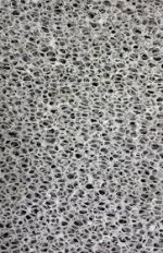
Attached is a scanning electron microscope image showing the pores in rubber. The pore sizes are in the order of 10-3 mm, much larger than air molecules which are in the order of 10-7 mm.
Attachments

Thanks, Galu.
That introduces an interesting question well worth contemplating during lock-down for Covid-19: can we devise a cab which includes a wall section which is functionally impervious to sound but porous for air molecules?
(In practice, that is what a small hole does. But of course we are looking for something that works below more than 3 meters of water.)
B.
Although the effect of Cms will vary with the driver chosen, my guess is that the influence is small because compliance forces are small.
Using the earlier example of:
P1 = 29.5 inches of mercury
P2 = 30.5 inches of mercury
V1 = 3 cubic feet
Diam =15 inches
Cms = 4.00E-04 metres/newton
Percentage value = 2.93% (49 cubic inches per cubic foot)
Halving the value of compliance Cms to 2.00E-04 metres/newton:
Percentage value = 2.57% (43 cubic inches per cubic foot)
The page linked below gives the following formula:
Percentage of Sag = 24849 / (Xmax * fs ^ 2)
Resources - Woofer Mount Up Down
The Sag can also be found directly, independent of the value of Xmax:
Sag = 248.49 / (fs ^ 2) = 248.49 / (51.62 ^ 2) = 0.09 millimetres
Just for the record, although close enough for all practical purposes, the formulas given on the webpage linked above and the expression Sag = 248.49 / (fs ^ 2) derived from them, are not completely accurate. The theoretically correct formula is Sag = 248.49 / (fs ^ 2) - Mma * Cms * 9.81 meaning that in addition to fs, Sd and Cms also need to be known.
Attachments
IMHO the limiting factor here is not the size of the air molecules, but how quickly the atmospheric pressure changes. Under extreme weather conditions the barometer can drop significantly over a couple of hours (not that one would be doing much listening to music under those conditions, he, he,). 😀The pin hole can be a small as you like, given that the diameter of an air molecule is 4 x 10⁻⁷ millimetre 🙂. Assuming that we are starting with a completely sealed system, a 1 millimetre diameter hole would be vastly more than sufficient to balance the barometric pressure on both sides of the diaphragm.
So let's say the pressure change happens over a period of 2 hours. In order to equalise the pressure, the air trapped inside the cabinet (now at a higher pressure than the atmosphere) has to pass through the hole without
a) creating a significant pressure differential - which is what we're trying to avoid in the first place.
b) travelling through the hole at a high velocity - which might make an undesirable whistling sound.
What speaker, prey tell, is completely sealed between the front of the cone and the back side of the basket?
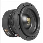
I bought one of these to make a pneumatic driver - basically I want a 6" syringe with an attached voice coil. Should be easy; they claim a solid, strong dust cap and the cone appears to be solid, thick piece of plastic. I put a shallow solid plastic cap over it to constrain the output to a 1/4" hose barb.
Leaks, leaks, leaks and leaks some more. I noticed the surround is sewn to the cone, so I covered that with GOOP cement, still leaks. I covered the dust cap, still leaks. Getting really frustrated, I painted the entire foam surround with this GOOP adhesive, made sure all the mounting holes were plugged, then glued the cap directly to the basket after removing the rubber gasket completely...
...Still leaks. I dont know what kind of drivers y'all are worried about not equalizing pressure in hours of time due to a barometric change, but I cant seem to make a given driver be airtight between front and back, no matter what I try.
I'm pretty sure the surround is porous. It's still porous after my glue treatment. Cant think of any possible path for the air pressure to get past that dustcap, cone and surround - but there is. Easily discernible just blowing into the hose barb with my mouth; better than before I went nuts with the GOOP, but nowhere near airtight.
Attachments
Last edited:
So let's say the pressure change happens over a period of 2 hours.
At a maximum, that could mean up to a 4 millibar change in pressure (at a rate of 0.0006 mbar/sec). I am pretty sure that a 1 millimetre diameter hole would have absolutely no problems in coping with that. My air molecule comment was a "tongue in cheek" observation (hence the smiley) simply to highlight the fact that the hole did not have to be very large at all. Up until then, there seemed to be some uncertainty among posters as to how large the hole had to be, assuming that the system was completely sealed. I was just trying to point out that in effect, the smallest practical drill bit size available would be more that adequate.
more that adequate.
Oops, should have said: "more than adequate." 🙂.
In the classic reference text book "Acoustics", Leo Beranek states that for a closed-box baffle "A slow air leak must be provided in the box so that changes in atmospheric pressure do not displace the neutral position of the diaphragm."
Presumably a 1 millimetre diameter hole would qualify as a slow air leak?
- Home
- Loudspeakers
- Subwoofers
- Equalize atmospheric pressure in sealed cabinets