Sorry, I didn't mean to offend🙂"You could probably calculate it using t/s parameters for the driver in question."
Golly Discopete, I am just not smart enough do know how to do that. Would you please do it for all of us. Just pick parameters (or some driver with T/S specs on Parts Express or shared otherwise) you find convenient to work with.
Ultimately, as I said before, all any of us want to know is very roughly how far will a cone move.
Thanks a million.
B.
There is no answer to your good question until we have some idea what the problem is.
Just guessing, I'd say (a) the atmospheric changes we are talking about happen so slowly a tiny hole is adequate to move the air in and out and (b) a hole that tiny is a lot smaller than the ordinary leaks in a cabinet* and even a somewhat bigger hole wouldn't matter to the speaker performance.
But still, let's figure out very roughly how much the air inside (and outside) a perfectly sealed cab would deflect the cone. Got to be simple physics with a touch of algebra.
B.
* don't we all carefully ponder how to overlap the weather-seal strips where they meet at the corner when we prepare to screw on the back panel?
Last edited:
The size of the hole shouldn't be too critical.
It seems it should be small enough not to significantly integrate driver non-linearity, and modulate the quiescent point on the fly.
It also seems it should be large enough to vent atmospheric variations over some time period, say hour to hour perhaps.
It seems it should be small enough not to significantly integrate driver non-linearity, and modulate the quiescent point on the fly.
It also seems it should be large enough to vent atmospheric variations over some time period, say hour to hour perhaps.
No. The variation in atmospheric pressure is about 1 PSI. I think 68 pounds was mentioned for a woofer with a cone surface area of 133 sq. inches.68psi more or less.
Last edited:
Well reasoned and explained.Using waterproof cones and mounting gaskets, it is possible (though unlikely) to make a completely air tight cabinet.
Air pressure (AKA barometric pressure) normally can vary from 980 millibars which equals 14.21 pounds per square inch to 1050mb, which is 15.23psi, a net difference of 1.02psi. Looking at current pressure maps shows readings from 991mb to 1024mb at one point in time on just one continent.
A 15" has around 133 square inches of cone area, 133 x 1.02= 135.66 pounds, assuming you seal the cabinet in the middle of the range, there is still about a 68 pound pressure swing that can be expected, more with extreme storm conditions which seem to be happening with more frequency.
Assuming 68 pounds of pressure on the cone does not actually tear the surround, it can certainly result in an offset great enough that the coil will easily bottom out, as well as the attendant distortion and sensitivity loss of a driver forced to operate with it's coil pushed out of the magnetic gap, whether rearward or forward offset. Good reasons why "sealed" cabinets are never designed to be "air tight".
Art
Note that changes in atmospheric pressure do not happen instantaneously, but over a few hours. The enclosure has to be leaky enough so that such changes are able to equalise. As mentioned earlier, with non-paper cones and better construction materials and techniques, like plastic moulded enclosures and industrial quality gaskets and sealants, it is possible to make the enclosure airtight - and that might not be a good thing.
Last edited:
A friend and I constructed a sub-woofer some 35 years ago to look like a coffee table. It was a down firing sealed enclosure, constructed from two layers of 19 mm particle board - box inside a box; the 20 mm space between the two layers was filled with bitumen. The top was a 25 mm solid kiaat (local hard wood) and the whole construct was almost impervious to vibration. The speaker hole mounting frame was also from kiaat. The speaker cone was doped with multiple coats, to drop the Fs by 4 Hz down to 23 Hz. Totally over engineered, but had an awesome effect on the overall sound. Was designed to go with a pair of MG 1-B speakers.
Being built at at 1300 m above SL, they definitely would have required pressure equalisation if taken down to the coast.😀
Being built at at 1300 m above SL, they definitely would have required pressure equalisation if taken down to the coast.😀
Last edited:
if I have a 3 cubic foot cab and a 15-inch driver, how far will the cone be displaced between a typical low atmosphere day and a high day?
As a first approximation, if the nominal outside atmospheric pressure is 14.7 psi and the pressure inside the cabinet is also 14.7 psi, then increasing the outside pressure by 1 psi will displace the driver diaphragm into the 3 cubic foot sealed cabinet by 1.87 inches, assuming that the diameter of the diaphragm is 15 inches, and that the effects of the diaphragm suspension mechanical compliance (Cms) can be neglected.
From Boyle's Law:
P1 * V1 = P2 * V2
14.7 * 3 = 15.7 * V2
V2 = 14.7 * 3 / 15.7 = 2.809 cubic feet
Reduction in volume = 3 - 2.809 = 0.191 cubic feet = 0.191 * 12 ^ 3 cubic inches
Diaphragm displacement = 0.191 * 12 ^ 3 / (Pi * 7.5 ^ 2) = 1.87 inches
Last edited:
Thanks very much. To the small degree that I understand these things, makes sense to me.As a first approximation, if the nominal outside atmospheric pressure is 14.7 psi and the pressure inside the cabinet is also 14.7 psi, then increasing the outside pressure by 1 psi will displace the driver diaphragm into the 3 cubic foot sealed cabinet by 1.87 inches, assuming that the diameter of the diaphragm is 15 inches, and that the effects of the diaphragm suspension mechanical compliance (Cms) can be neglected.....
Diaphragm displacement = 0.191 * 12 ^ 3 / (Pi * 7.5 ^ 2) = 1.87 inches
Quite a gigantic bulge that would be quite obvious to any sober audiophile - it would have destroyed any driver under 21 inches in a sealed box. And evil would befall anybody from Miami who bought a sealed speaker made in Colorado or Switzerland and with reciprocity. And if a person's cones aren't buldging in or out with the weather, they haven't made themself a sealed box.
You've used a change of about 7%. But isn't a more typical change 29.5 to 30.5 "inches" which is 3% and still pretty gross? Either way, nice to have your judgment that a pin hole (or ordinary leak) sure is essential.
There remains the empirical question of how air-tight a given DIY "sealed" cab is, even with good carpentry skills.
Again, thanks.
B.
Last edited:
But isn't a more typical change 29.5 to 30.5 "inches"
In that case, P1 would be 14.489 psi and P2 would be 14.980 psi, resulting in a diaphragm displacement of 0.96 inch.
Incidentally, the reason why Cms can be safely neglected in this analysis is because the "equivalent resisting pressure" resulting from the suspension stiffness (1 / Cms) is very small compared to the other pressure values being considered in the system.
Assuming a linear system with Cms = 4.00E-04 m/newton and diaphragm displacement = 0.96 inch:
Stiffness = 1 / Cms = 2500 newtons/m = 2500 * 0.224809 = 562 pounds-force/m
Stiffness = 562 / (100 / 2.54) = 14.275 pounds-force/inch
Force = 14.275 * 0.96 = 13.704 pounds-force
Equivalent resisting pressure exerted due to suspension stiffness = 13.704 / (Pi * 7.5 ^ 2) = 0.08 psi
That's a heady mixture of imperial and metric units in there, David!
I was about to ask whether or not it was permissible to neglect Cms and, lo and behold, you've already anticipated my question!
Thanks for going that extra mile - or should that be kilometre!
I was about to ask whether or not it was permissible to neglect Cms and, lo and behold, you've already anticipated my question!
Thanks for going that extra mile - or should that be kilometre!
I was about to ask whether or not it was permissible to neglect Cms and, lo and behold, you've already anticipated my question!
Hi Galu,
Just to make sure, I have now checked how much the the displacement value would actually change if Cms was indeed taken into account 🙂.
The relationship between the various parameters is as follows:
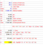
P2 = P1 * V1 / (V1 - X * Sd) + X / (Cms * Sd)
The expression is a quadratic equation and can solved for displacement X directly.
If we assume the following:
P1 = 29.5 inches of mercury
P2 = 30.5 inches of mercury
V1 = 3 cubic feet
Sd = 176.71 square inches (15 inch diaphragm diameter)
Cms = 4.00E-04 metres/newton
Then after converting all units as appropriate, rearranging and manipulating the quadratic equation, and working through the calculations, for a linear system the value of the displacement becomes 0.83 inches, compared to the figure of 0.96 inches previously obtained when Cms was not taken into account.
Kind regards,
David
EDIT
There is a bracket missing in the worksheet formula (-B + Sqrt(B ^ 2 - 4 * A * C) / (2 * A) it should be (-B + Sqrt(B ^ 2 - 4 * A * C)) / (2 * A).
Similarly for (-B - Sqrt(B ^ 2 - 4 * A * C) / (2 * A).
The formulas used in the actual calculations are correct.
Attachments
Last edited:
Wonderful. Thanks again. A knowledge of physics and a bit of algebra and we now know the answer (even considering the little bit of spring force pushing back by the spider).
And now, in a display of my grasp of arithmetic, I think David has estimated a change of one inch of Mercury expands the enclosed air by 50 cu inches per cu foot (taking the spider into account) which is 3% change. The net effect on the cone(s) is plus and minus 25 cu in. from the driver resting point for each cu foot enclosed volume.
One inch of mercury is about the range my home might get in a typical month. at least in Toronto or Delray Beach, FL.
So now others using 5th grade arithmetic can figure their box size and speaker surface and know the answer (hint: cones smaller than a nominal "15 inches" will move a lot more).
So if you don't see your sealed box cone move when the weather changes, you are lucky you have a leak. If you are sealed and if your speaker is like David's example, you better hope your Xmax is one inch or more - lotsa luck with that.
Please double-check this.
B>
Last edited:
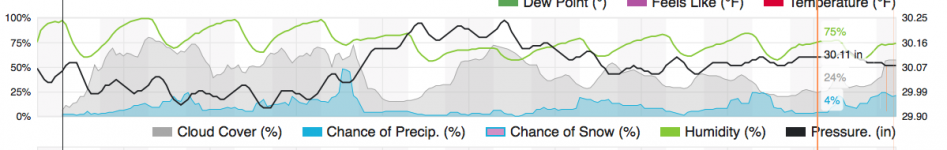
Now to try to answer OP's original question, attached is the height of mercury in Delray Beach, FL, predicted this coming 10 days. See the heavy black line.
The cross-section of the pin hole must accommodate the mostly slow rate of change of the barometric pressure illustrated in this prediction, using David's calculation.
Easy.
B.
The cross-section of the pin hole must accommodate the mostly slow rate of change of the barometric pressure illustrated in this prediction, using David's calculation.
Easy.
B.
Attachments
Much appreciated! 😎Hi Galu,
Just to make sure, I have now checked how much the the displacement value would actually change if Cms was indeed taken into account 🙂.
I appreciate the calculations made by David McBean, but anyway, not even considering an airtight cabinet, with a perfect seal between the gasket of the basket and the baffle, super resistant speaker materials for the surround, the cone and the dust cover, Premium adhesives etc - which is not my case - I think you would never get a 1 inch offset as some people say....😱
Perhaps in extreme circumstances of variation in atmospheric pressure ......
Buenos Aires is at sea level, the normal pressure should be 1017 hpa for this city, luckily we do not have tropical storms here, but in that case the least I would worry about would be my subwoofers ...😀
Perhaps in extreme circumstances of variation in atmospheric pressure ......
Buenos Aires is at sea level, the normal pressure should be 1017 hpa for this city, luckily we do not have tropical storms here, but in that case the least I would worry about would be my subwoofers ...😀
I see that there has been no response to my concern expressed in post 50.
Maybe you didn't read the full Audioholics article, so I'll copy the part that piqued my interest here.
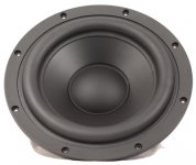
SB Acoustics SB34SWPL-76-4 12" Subwoofer Driver
" This looks promising as an acoustic suspension woofer: FAR of 19 Hz and a Qts of .33
But this is far more typical of today’s subwoofer drivers: FAR of 28 Hz and a Qts of .48. Beautiful driver—beefy, well-made, aluminum cone, no doubt a monster of a woofer, as long as it’s mounted in a vented cabinet of the appropriate size (3.0 cu. ft. or more). But as physically “impressive” as this driver is, it would never reach -3 dB into the low 30-Hz range passively—unaided by rather drastic response-shaping electronic EQ—in an enclosure of 1.5 cu. ft.
Drivers such as these with an FAR above 23-30Hz are simply unsuited to being used in true, optimized acoustic suspension systems. If they are used in a sealed system, excessive electronic EQ is required to achieve a reasonable LF extension because the “organic” (passive) response of a sealed system using a driver like this in an enclosure of 1.5-2.0 cu. ft. will have a -3 dB point of 40-60 Hz at best. It’ll take a lot of amplifier power to EQ its way down to 20 Hz, power that will no longer be available for overall system SPL. Remember, every additional 3 dB of SPL requires a doubling of amplifier power. The difference between 6 dB of LF EQ and 12 dB of LF EQ is 4 times the power! Like former president John Adams said, “Facts are inconvenient things.”
The on-board power in a subwoofer (an expensive and quite finite commodity, after all) is being “wasted” on EQ because the system’s passive response gives up the ghost at 55 Hz instead of 35 Hz. And you can be sure these new woofers—optimized for vented cabinets—wouldn’t even be in a nearby universe of -3 dB at 35 Hz in a sealed enclosure as small as 1.48 cu. ft.
The drivers used in today’s “sealed” subwoofers are not acoustic suspension drivers. The majority of the restoring force is not provided by the air spring in the subwoofer’s enclosure, as would be the case in a true acoustic suspension system using a very high-compliance driver. In fact—amazingly, unbelievably—many of these manufacturers use the exact same driver in both the ported and sealed versions of their subwoofer. Since it is used in the vented system (and that system performs so well), one can safely assume the driver’s Q is well above .4-.45. That means that it is optimized for ported use and badly mismatched for a sealed application, or that both of the applications are unsatisfying compromises. A driver is either optimized to be a ported driver or an acoustic suspension driver. It can’t be both.
But….if these manufacturers had optimized a second version of their woofer specifically for use as a true acoustic suspension driver, what a truly great product that would be. Less LF EQ would be necessary for the system to reach the same-3 dB LF point than is currently the case with a high-Q woofer in a small sealed enclosure, so more power would be available for sheer output. The system would play louder with the same bass extension. Or, you could make the enclosure even smaller, which would require a bit more EQ, probably on the order of what those actual small sealed subs are using now. So a true acoustic suspension compact subwoofer would either play louder at the same size or play as loud, but in a smaller enclosure. Either way, it’s a better product in my opinion.
The only obstacle to getting a great product like this is that the engineers would have to know the ins and outs of real acoustic suspension design. Which they don’t (or they choose to ignore, unfortunately). So instead of great small acoustic suspension subs that will play loud and low from a small enclosure, with great transient response, low THD over their usable band and a very gradual 12 dB/oct. rolloff—perfect for real-life family rooms of, say, 2000 cu. ft, what we have instead are ‘sealed sub’ compromises, which are merely very good products.
But they’re not as good as they could—and should—be. Why settle for B+ or A when A+ is easily attainable? "
Sealed is Not Acoustic Suspension in Loudspeakers | Audioholics
Maybe you didn't read the full Audioholics article, so I'll copy the part that piqued my interest here.
SB Acoustics SB34SWPL-76-4 12" Subwoofer Driver
" This looks promising as an acoustic suspension woofer: FAR of 19 Hz and a Qts of .33
But this is far more typical of today’s subwoofer drivers: FAR of 28 Hz and a Qts of .48. Beautiful driver—beefy, well-made, aluminum cone, no doubt a monster of a woofer, as long as it’s mounted in a vented cabinet of the appropriate size (3.0 cu. ft. or more). But as physically “impressive” as this driver is, it would never reach -3 dB into the low 30-Hz range passively—unaided by rather drastic response-shaping electronic EQ—in an enclosure of 1.5 cu. ft.
Drivers such as these with an FAR above 23-30Hz are simply unsuited to being used in true, optimized acoustic suspension systems. If they are used in a sealed system, excessive electronic EQ is required to achieve a reasonable LF extension because the “organic” (passive) response of a sealed system using a driver like this in an enclosure of 1.5-2.0 cu. ft. will have a -3 dB point of 40-60 Hz at best. It’ll take a lot of amplifier power to EQ its way down to 20 Hz, power that will no longer be available for overall system SPL. Remember, every additional 3 dB of SPL requires a doubling of amplifier power. The difference between 6 dB of LF EQ and 12 dB of LF EQ is 4 times the power! Like former president John Adams said, “Facts are inconvenient things.”
The on-board power in a subwoofer (an expensive and quite finite commodity, after all) is being “wasted” on EQ because the system’s passive response gives up the ghost at 55 Hz instead of 35 Hz. And you can be sure these new woofers—optimized for vented cabinets—wouldn’t even be in a nearby universe of -3 dB at 35 Hz in a sealed enclosure as small as 1.48 cu. ft.
The drivers used in today’s “sealed” subwoofers are not acoustic suspension drivers. The majority of the restoring force is not provided by the air spring in the subwoofer’s enclosure, as would be the case in a true acoustic suspension system using a very high-compliance driver. In fact—amazingly, unbelievably—many of these manufacturers use the exact same driver in both the ported and sealed versions of their subwoofer. Since it is used in the vented system (and that system performs so well), one can safely assume the driver’s Q is well above .4-.45. That means that it is optimized for ported use and badly mismatched for a sealed application, or that both of the applications are unsatisfying compromises. A driver is either optimized to be a ported driver or an acoustic suspension driver. It can’t be both.
But….if these manufacturers had optimized a second version of their woofer specifically for use as a true acoustic suspension driver, what a truly great product that would be. Less LF EQ would be necessary for the system to reach the same-3 dB LF point than is currently the case with a high-Q woofer in a small sealed enclosure, so more power would be available for sheer output. The system would play louder with the same bass extension. Or, you could make the enclosure even smaller, which would require a bit more EQ, probably on the order of what those actual small sealed subs are using now. So a true acoustic suspension compact subwoofer would either play louder at the same size or play as loud, but in a smaller enclosure. Either way, it’s a better product in my opinion.
The only obstacle to getting a great product like this is that the engineers would have to know the ins and outs of real acoustic suspension design. Which they don’t (or they choose to ignore, unfortunately). So instead of great small acoustic suspension subs that will play loud and low from a small enclosure, with great transient response, low THD over their usable band and a very gradual 12 dB/oct. rolloff—perfect for real-life family rooms of, say, 2000 cu. ft, what we have instead are ‘sealed sub’ compromises, which are merely very good products.
But they’re not as good as they could—and should—be. Why settle for B+ or A when A+ is easily attainable? "
Sealed is Not Acoustic Suspension in Loudspeakers | Audioholics
Attachments
I think David has estimated a change of one inch of Mercury expands the enclosed air by 50 cu inches per cu foot (taking the spider into account)
Just to clarify - changing V1 from 3 cubic feet, driver diaphragm diameter from 15 inches, or Cms from 4.00E-04 metres/newton, will change the resulting 'cubic inches per cubic foot' figure. The figure will also change slightly depending on the chosen values for the two pressures differing by 1 inch of mercury. For example, 29.5 in Hg and 30.5 in Hg will give a slightly different result to 29.0 in Hg and 30.0 in Hg.
My curiosity got the better of me 🙂. Although not a directly-related matter, I couldn't resist also checking how much the driver diaphragm would "sag" in a down-firing loudspeaker. Assuming that the static air pressures are the same on both sides of the diaphragm, the relevant formula for a linear system becomes:
Sag = Mmd * Cms * 9.80665
Where Sag is in millimetres, Mmd in grams, and Cms in metres/newton.
In the case of the Hornresp default driver:
Mmd = 20 grams
Cms = 4.00E-04 metres/newton
Sag = 20 * 4.00E-04 * 9.80665 = 0.08 millimetres
The page linked below gives the following formula:
Percentage of Sag = 24849 / (Xmax * fs ^ 2)
Resources - Woofer Mount Up Down
In the case of the Hornresp default driver:
Xmax = 5.0 mm
fs = 51.62 hertz
Percentage of Sag = 24849 / (5.0 * 51.62 ^ 2) = 1.87%
Sag = 5.0 * 1.87% = 0.09 millimetres (very close to my 0.08 mm result above)
The Sag can also be found directly, independent of the value of Xmax:
Sag = 248.49 / (fs ^ 2) = 248.49 / (51.62 ^ 2) = 0.09 millimetres
Thanks for sag calculation.
20 grams!!! Some woofers are 200 grams and more. Doesn't getting that particular parameter representative have a very large influence on sag?
B.
20 grams!!! Some woofers are 200 grams and more. Doesn't getting that particular parameter representative have a very large influence on sag?
B.
- Home
- Loudspeakers
- Subwoofers
- Equalize atmospheric pressure in sealed cabinets