PORT EnABL - A New Frontier...
G'day zBuff,
I have resisted posting about ports in this thread until now.
Port EnABL. is a very new application of EnABL that needs more investigation.
However, I have consistently seen audible changes when treating ports.
PORT ENABL
Use this EnABL block size calculator to determine the size of the blocks.
NOTE: Use 9 - 10 block pairs for ports (not 18 as you do with a driver)
Please note that the number of blocks pairs is ONLY a starting point for exploration.
- I have not used paint on the ports
- I have not used ANY conformal coating
Parts list:
- Scotch Magic Tape (19mm)
- Duct tape (PVC) (48mm)
- Cutting knife or blade
- Cutting Mat
- Ruler
Instructions
1. Lay a strip of Scotch Magic tape sticky side down on a cutting mat
2. Lay a strip of duct tape sticky side down also on the cutting mat
3. Using a blade, cut the duct tape into the right size blocks for the port
4. Pick the blocks off the cutting mat using the blade
5. Stick the blocks on top of the Magic tape in the EnABL pattern
6. Trim off excess Magic tape to about 1-2 mm from the top and bottom edge of the EnABL pattern, and flush with the blocks at the ends
7. Peel up the Magic tape with EnABL'd blocks
8. Stick into port
The common success factor I have observed is that the port/s being treated must directly load the driver.
Best results so far (subs and multi-way) have come from situations where:
- the driver fires into free air and
- the driver is loaded exclusively by the port
- the port is round and straight (no flare)
I have only been able to apply the EnABL pattern at one end of the port (with the exception of one subwoofer, where the pattern was applied roughly halfway in).
Bass Reflex cabinets have so far provided the most obvious audible changes.
This is for both subwoofers and ported multi-way speakers.
I have Voight pipes, which are a hybrid between horn and MLTL (I think).
These have responded very well to EnABL port treatment also.
For Band Pass cabinets with an internal ported cavity, treating the final port does not seem to generate the same magnitude of change.
Ideally, you would need to EnABL the internal port/s as well.
For ported subwoofers with downward firing drivers, the driver is loaded by both the port and the space between baffle and the floor
So you will need to EnABL the baffle as well.
Ideally the subwoofer should be mounted on a hard flat surface (concrete or MDF board) with the same dimensions as the baffle, and the EnABL pattern applied as well.
Flared Ports
On the flared ports I have treated, they were all sub-woofers and the driver was usually down firing or the box was a band pass design with the driver enclosed.
I have only applied the pattern in the straight part of the port just before the flare.
Here are a couple of ideas that are worth trying: (I would have, but the owners of the speakers wouldn't let me pull them apart!)
1) Apply the pattern to the port where the flare becomes flush with the baffle (measure the diameter and that point and caluculate block size accordingly)
2) Apply the pattern to the inside of the port at the opposite end to the flare
Can I emphasise the point that THIS IS A COMPLETELY NEW APPLICATION OF ENABL.
There is no 'ideal' or 'best' approach yet, only a starting point to explore.
I'm happy to answer any questions.
Cheers,
Alex
zBuff said:Sorry Alex, wasn't clear enough on my last post. Yes I tried it on a port.
I was hoping for an improvement as the improvement to to drivers using the cone treatment is fantastic.
I will try again on a system I can A-B test, and let you know how it goes. If it's on a flared port, do you place it before the flare begins or at the end of it?
G'day zBuff,
I have resisted posting about ports in this thread until now.
Port EnABL. is a very new application of EnABL that needs more investigation.
However, I have consistently seen audible changes when treating ports.
PORT ENABL
Use this EnABL block size calculator to determine the size of the blocks.
NOTE: Use 9 - 10 block pairs for ports (not 18 as you do with a driver)
Please note that the number of blocks pairs is ONLY a starting point for exploration.
- I have not used paint on the ports
- I have not used ANY conformal coating
Parts list:
- Scotch Magic Tape (19mm)
- Duct tape (PVC) (48mm)
- Cutting knife or blade
- Cutting Mat
- Ruler
Instructions
1. Lay a strip of Scotch Magic tape sticky side down on a cutting mat
2. Lay a strip of duct tape sticky side down also on the cutting mat
3. Using a blade, cut the duct tape into the right size blocks for the port
4. Pick the blocks off the cutting mat using the blade
5. Stick the blocks on top of the Magic tape in the EnABL pattern
6. Trim off excess Magic tape to about 1-2 mm from the top and bottom edge of the EnABL pattern, and flush with the blocks at the ends
7. Peel up the Magic tape with EnABL'd blocks
8. Stick into port
The common success factor I have observed is that the port/s being treated must directly load the driver.
Best results so far (subs and multi-way) have come from situations where:
- the driver fires into free air and
- the driver is loaded exclusively by the port
- the port is round and straight (no flare)
I have only been able to apply the EnABL pattern at one end of the port (with the exception of one subwoofer, where the pattern was applied roughly halfway in).
Bass Reflex cabinets have so far provided the most obvious audible changes.
This is for both subwoofers and ported multi-way speakers.
I have Voight pipes, which are a hybrid between horn and MLTL (I think).
These have responded very well to EnABL port treatment also.
For Band Pass cabinets with an internal ported cavity, treating the final port does not seem to generate the same magnitude of change.
Ideally, you would need to EnABL the internal port/s as well.
For ported subwoofers with downward firing drivers, the driver is loaded by both the port and the space between baffle and the floor
So you will need to EnABL the baffle as well.
Ideally the subwoofer should be mounted on a hard flat surface (concrete or MDF board) with the same dimensions as the baffle, and the EnABL pattern applied as well.
Flared Ports
On the flared ports I have treated, they were all sub-woofers and the driver was usually down firing or the box was a band pass design with the driver enclosed.
I have only applied the pattern in the straight part of the port just before the flare.
Here are a couple of ideas that are worth trying: (I would have, but the owners of the speakers wouldn't let me pull them apart!)
1) Apply the pattern to the port where the flare becomes flush with the baffle (measure the diameter and that point and caluculate block size accordingly)
2) Apply the pattern to the inside of the port at the opposite end to the flare
Can I emphasise the point that THIS IS A COMPLETELY NEW APPLICATION OF ENABL.
There is no 'ideal' or 'best' approach yet, only a starting point to explore.
I'm happy to answer any questions.
Cheers,
Alex
Fostex F 200 A
This is a complex speaker treatment for EnABL. Fostex has applied an ever sticky damping material to a section of the back side of the cone. They have also filled the front side with a damping compound and applied what appears to be a significant amount of damping material to the back side of the aluminum center dome/voice coil cover.
All of this material does provide a smooth frequency response. However, unless you are within 5 degrees of on center, it also limits all sound to the lifeless category. On axis the sound is quite good at low levels, but as the level increases all sounds become rounded on the leading edge and while there is a fair amount of coherent decay information, it cuts off quickly.
None of this is bad. It also keeps the driver from emitting shrieks under transient duress. The Alnico magnet structure also lends it's typical sweetness to the sound reproduced. Within these limits, this a very respectable driver, but not competition for most other high quality full range drivers. We can fix this.
Patterns, front side.
I have provided small alignment lines, in red, to aid in aligning the pattern block sets, for visual satisfaction. Misalignment will not affect performance.
Use a number 3 pin tip for the outer pattern ring set. This is slightly too wide so allow a little more space between rings of blocks.
The mid cone ring set needs a number 4 pen tip and the patterns should be applied with the bottom ring set just slightly further up the cone than where the pattern rests. Do cut out the middle section carefully, so you can center this set of rings very closely.
The inner patterns on cone and dome are seperate, full patterns sets. You can use the same ring for both. The inner patterns on cone and dome can be applied with a number 56 pen tip.
The dome mid ring also needs that number 56 pen tip and should also be centered with care. Then, apply the usual six block sets in two rings with a center circle of about 1/16th inch in diameter Look here for the pictures that will make more sense out of these words.
http://picasaweb.google.com/hpurvine/FostexF200A
Patterns, back side.
Use the back side inner ring set, for the patterns applied to just inside the inner diameter of the damping material on the back side of the cone. It is useful to apply the outer ring set as close to the damping material as you can, without actually getting it onto that sticky stuff. This conic section is going to be a PITA to get onto the cone.
Best method seems to be to leave a tail end sticking straight up, while feeding the leading edge under the tinsel connection wires, from the next open sector around. After you have it where it needs to be, a pieces of tape across the joint will help you to align it properly. I ended up using long nosed pliers and blue language to help get it sorted out. Use a number 4 pen tip with a radial pen holder orientation and plan to place blobs, rather than neatly shaped blocks here. For the blocks behind the cast frame stanchions, use a corner of the pen tip. These will, of course, be the neatest blocks in the ring sets.
The outer ring needs a number 3 pen tip and is quite straight forward and easy to apply, with the only difficult parts also behind the stanchions. Again refer to the photos and feel free to download them, so you can look closely at them, as they are high resolution for just this purpose.
Gloss coating, front side.
Use a 3/8 inch wide, sable hair, flat, wide area water color brush for this driver. The first coat of gloss is applied in the center of a four block set sector, in a radial stroke. The brush was one side tamp drained and the gloss was cut 50% with clean water. Apply only a light pressure from cone bottom to surround edge. Then quickly apply two strokes, on either side of the first and then rebrush at all of them, sipping material off of the surface of the center stroke and applying it to the two outer strokes. This should cover a full, four block set arc, on the cone patterns. There will be some openings out at the top section. Make as even a job of this coat as you can. The material will not soak in to any great degree, so you have plenty of time to be picky about this procedure. Do your best to keep gloss material off of the semi soft joint material, down at the cone/dome joint, as much as possible
After 24 hours of set time listen to the drivers for a short time. There should be a broader arc of high frequency information and a considerably better defined leading edge to notes and longer decay periods to instruments that naturally have them.
The second coat, on the front cone face, will be circumferential. Use a one side tamp drained brush load per stroke. The strokes should cover 1/4 of the circumference per brush load, using very light pressure. You will not empty the brush except on the last, outer most stroke. Let this entire coating dry for a day.
The third coating is very light. Use a both side tamp drained brush load and, with radial strokes coat an entire quarter arc of the cone. This will be relatively easy, but work quickly , use both sides of the brush, and a light pressure.
Next apply a coating to the dome, still keeping material off of the semi soft joint material as much as possible. Use a one side tamped brush load and with full diameter strokes coat about one half of the dome. Re dip the brush and tamp drain one side and coat the remaining dome surface . Smooth out any obvious problems and let everything dry for a day. Now put one brush load from a thin pointed brush, on the semi soft damping material, in a circumferential stroke. Smooth this out and let the gloss material blend into the cone and dome coatings slightly.
After a day, apply two drops of PVA to the center circle, at the dome center. Both should be full body of a round wood toothpick barrel in diameter. Apply the first, turn the driver upside down and allow the droplet to dry. Then apply the second right on top and again allow to dry upside down. After about 4 hours of cure, use that pointed brush to apply just a little bit of gloss coating over the PVA droplets.
Spend some more time listening. If you are satisfied with the sound, the amount of detail, decay periods and transient attack, stop here. Further treatment is going to require patience and a delicate touch.
I have attached the full pattern set, as a three page PDF file. In another post I will cover the rest of the pattern and gloss treatment. If you are courageous, the results are more than worth the time spent. If you stop here, you will still have one of the best sounding drivers available. Smooth, clear, with a surprising sound stage depth and width. The various components of musical instruments will be balanced and your ability to hear into complex music will astonish you. This is indeed a very special speaker.
Bud
Attachments
Fostex F 200 A, part two.
Those of you who have looked over the pictures and patterns will have noticed that there is a ring set on the outer aluminum Fascia and on the vertical wall that makes a lip for the surround to be glued to. If you are going to apply the extended process this pattern is the first step. I used the flat clear Poly S paint and a number 3 pen tip here.
Applying it commits you to the rest of the process, so think about it before starting. This outer ring will unlock a torrent of high frequency information. The sound field will become distressed, instruments will loose their precise place and the entire event will seem to be suddenly dull, right after the leading edge has occurred.
This step in the frame is a collection and emission control step, just as it was on the Hemp Acoustics FR 4.5c. Placing a pattern on it removes this and kills the specificity of speaker position that it causes, slight as that actually is. As for the signal content, it is more like breaching a dike than anything else.
A single coat of gloss over this pattern and on out to the edge of the turned bright metal surface is all for now, here.
The next step to this application consists of applying Gloss to the back side, very carefully and in an odd sort of pattern. Using 50% cut Gloss coat, as everywhere else on this driver, apply a single brush width in a circumferential ring around and over the pattern ring set, on the outer edge of the cone back side. Then a brush width over the sticky damping material, which will require two 3/8" wide brush widths, and so on until you have applied Gloss to one brush width past the inner pattern, which will leave the steepest portion of the curve in the cone uncoated and just about 1 brush width wide. You must not put gloss on this last 3/8 of an inch, inner most portion, of the cone back side.
The application pattern is the odd part. Using a single side tamp drain brush load, start under any of the four stanchions and draw the brush stroke toward the middle of the open zone, then do the same sort of brush stroke from the stanchion at the other side, back out to the middle. Rotate the driver 1/4 turn and repeat this process, using another brush load. Apply very light pressure, you really do not want to apply very much material on any portion of the back side. You still do not want to apply any to that most vertical portion of the cone, just before it joins the spider and voice coil assembly. The sticky portion will loose about half of it's sticky character, when the Gloss dries.
Let all of this cure for two day and listen to the drivers as they cure. You should end up with a pretty bright, very articulate sound, with that odd dullness after transient attack, no longer audible. This is not a bad sound, but it is annoyingly bright. It is also ridiculously clear and has a huge sound stage projection.
Next to last step is to recoat the bright aluminum bezel, vertical step wall and outer edge of the surround, that is glued to the bezel with 1 coat of 50% gloss.
The last step is to take a single brush load of gloss and two side tamp drain it, twice. With this you very lightly brush over the surround and down to the joint with the cone. This should just barely darken the surface of the surround. After this is dry run your finger around the surround, dimpling it in to flat for a couple pf circles. This and the final coat of Gloss, over the bezel will bring the brightness down to an even match with the mids and open up the sound field depth and level of detail.
Applying the patterns on the back of the cone and adding Gloss to those surfaces and the patterns on the bezel step and over the surround, will remove a graining of the sound field to a level perhaps 30% smoother. It will also add that much transparency to the layers of instruments in an orchestra.
The drivers, here in my listening room, are the best speakers I have ever heard. This includes all of the multiway and single driver speakers I have ever treated, or encountered. I am just amazed. They even have bass down below 100 Hz, while mounted nude on the usual stands.
I still intend to build the ridiculous Space Invader omni /open baffle/ transmission line speakers for the Lowther PM6A drivers, I think so highly of. But, I will have to somehow obtain a pair of these, perhaps to mate with yet another pair of Tang Band 8 inch bass drivers, in some even more foolish looking transmission line device.
These things are just superb.
Bud
Hi all, Some cautionary comments on the F 200 A and other expensive drivers
John K brought up a relevant point over on the technical thread, among his many others. He pointed out that these are an $800 plus investment for anyone. Unlike the relatively inexpensive drivers from Hemp Acoustics and smaller Fostex drivers, if you were to treat these, without paying close and careful attention to the instructions, you would be courting an expensive disaster.
While I am confident in my own skill set and am able to draw upon a large body of experience, when initially devising the treatment regimen for the drivers I have posted pattern tools for, most of you are not experienced and so should not be confident. Not even with my patterns and instructions right in front of you.
These are relatively simple things to do to a driver, using simple straight forward tools, to apply patterns and Gloss coat. Do not be deceived by this seeming simplicity, these tools will not, by themselves, ensure you will be able to successfully apply EnABL, to any driver, much less one with this many patterns and this level of specific application of gloss materials.
You absolutely must practice with pens and brush, using the materials shown. You can use a good quality "construction paper" for practice. It will also be very beneficial to use a light colored paint, so you get direct feed back upon your pen technique. Learning what a brush looks like, when single side tamp drain of the brush load, is used is CRUCIAL to applying the Gloss material.
After some practice on a flat surface you must move on to simple cones. Most of you will have some sitting around, and are not very impressed with how they sound now, so, why would you bother to EnABL them? PRACTICE!!!! Applying a pen stroke upon a three axis curve is not a trivial skill. Nothing hard, or deadly about it, but your first cone is going to look pretty bad, so don't make it an expensive one.
Another reason to practice is that really cheap speakers improve in clarity, transient accuracy and low level coherency to a much greater degree than their better engineered and more expensive cousins. Your cheap, EnABL'd, drivers will astonish you, with their capabilities uncovered.
Now, for those of you who have downloaded the pattern sheets and are thinking about treating your speakers, please heed the following words. Applying just the cone and dome patterns is straight forward, if you have a solid, trained, skill set. Applying the Gloss coat to the front surfaces is also quite straight forward, if you follow the instructions. Unless you have at least 6 pairs of other drivers under your belt, DO NOT APPLY THE OUTER RING SET ON THE SHINY ALUMINUM BEZEL AND VERTICAL LIP!!!
Applying this ring set really does unlock this drivers containment, via the front bezel step. Once you do this, it will become quite apparent that you will need to apply the back side patterns and also apply the very light coating of gloss described for the back side. The back side patterns, by themselves, will not change what you hear, other than to remove a slight but audible graininess. The addition of the gloss, from one 3/8" brush width below the inner, back side pattern, out to the cone join with the surround, will make a profound difference to what you hear, from the front side. This is the only place where you can really screw up. You can recover from a screw up here, but it will be tedious and worrisome.
So, before you attempt to treat this driver, practice extensively. The results of the practice and extended anticipation, will be more than worth the effort.
Bud
Thanks to Ed, I now have the materials to try EnABL on a cheapo pair of speakers - some Pinnacles. Main driver is a 3" cone that measures 2.5" on the inside of the surround attachment. See photos below. Since the cone is so small and the surround attachment is so relatively big, I'm wondering where the outer pattern ring should go - inside of the surround attachment on the paper cone itself, or farther out onto the surround attachment? Also, what about patterns on the inner cone next to the voice coil dome and on the dome itself? What about the back side of the cone, the metal frame, etc.? I see lots of what seem to be variants (especially Bud's last posts) and can't make sense of what's required and/or what's ideal. Will just the outer pattern on the front side work or are all locations required? 
TIA,
Carl
TIA,
Carl
An externally hosted image should be here but it was not working when we last tested it.
An externally hosted image should be here but it was not working when we last tested it.
Hi Carl,
Here is a preliminary look at what patterns you need and where I would place them.
We can get more detailed if you need to but I will need some measurements that are down to 0.005 inches in variance from reality, in specific places. Or, you can use a % of resize print out from one of the PDF files of patterns available, or if you have Corel Draw or Illustrator, I can provide vector files that you can scale exactly to size, for pattern templates. All can be done quickly too,
Bud
Attachments
Hi Bud,
Another question.
The most notable effect as cone diameter increases is beaming.
Your main patterns tend to be at cone centre and edge - both regions significantly related to beaming.
Have you ever noticed whether EnABL modifies a driver's beaming (diametric-edge related) characteristic, because selectively modifying a driver's beaming characteristic without modifying the overall energy it transduces will affect what we hear ?
Cheers ........ Graham.
Bud,
I have some tiny Q-acoustics 1010 lying around. The driver is described as:
Bass Driver 100mm bespoke fibre cone
Q 1010
It has quite a shiny surface - I am tempted to roughen it very slightly as a key then enabl it following the pattern you described above for the little Pinnacles.
Probably won't use a conformal coating.
If it was paper I wouldn't hesitate - it's not ... ?
Alan
Thanks a ton, Bud. I think I get it. On the three patterns I see near the dome, one is on the dome and two on the cone, or the other way around? I might be able to use the vector files so if they are available they would probably be a big help. I don't have a caliper so probably can't get you that close a measurement as yet. May change that soon, though. Finally, how significant is the pattern on the metal flange? I don't recall that being talked about when I first looked at the EnABL thread. Is it a new finding?
Carl
Carl
Graham Maynard,
One of the major reasons for treating a driver is to spread the on axis signal out until it is available across the swept area of whatever is the final physical wall. For straight wall cones this is the included angle of the main cone, regardless of whether or not there is a whizzer cone. For curved cones this is an angle approximately tangent to the break over portion of the curve into a straight walled cone, so usually a narrower angle than in a straight walled cone.
For domes, as in a Vifa 3 inch mid range dome, this included angle can approach 180 degrees. For flat radiators this angle is determined by what ever lens device they make use of and how it controls the emissions.
The typical treated driver has no hot spot, has no lobes and the same sonic character across a broad angle. Most treated speakers do not sound different toed in or flat to the room. Toed out can get a bit odd sounding.
Alan Hope.
The cone looks to be a molded plastic cone. You will have to "tooth" the plastic in most cases. I use an 800 to 1200 grit, wet/dry sand paper, with a small amount of water for lubricant, for this.
I suspect you will need to apply gloss just to get the full benefit from the patterns. This will be one of those times when you wonder if there might not actually be some sort of surface effect occurring.
If the plastic is a filled polypropylene, as is found in Dyna Vox drivers, you will need about ten coats of Gloss. At that point the driver will be very well, behaved, very clear, but a bit "slow" in comparison to cloth dome tweeters. Although it will be quite a bit more capable with transient signals than when left untreated.
If it is a lighter, unfilled plastic, as is more likely here, then it would not hurt to gloss coat the prepared cone with one coat first, apply the patterns and then recoat the cone one more time. I am not sure what plastics this will prove true upon, as I have only treated about thirty different plastic drivers, but to date this seems to be the most successful route.
If we view this as a local mass / stiffness event, the acrylic paint is not going to provide much effect. Using the gloss as an underlayment and as an overcoat will aid in this differentiation of local area mass. How you go about experimenting here is of course your business and if you just apply the patterns, I will be very interested to hear your take on the results.
Carl P,
The pattern set on the dome / cone joint is a reduction of two complete patterns, one for dome and one for cone, into a three ring circus. This works just as well as two full sets of patterns and is slightly less tedious to do. The middle ring is actually centered in the valley between the cone and dome. This usually places it on the dome surface, but it is the location that matters not which portion of which surface it is actually on. The other two rings go up on their respective walls the usual one block width space.
Also note that the outer pattern is half on the surround glue flange and half on the cone. This will prove to be important.
The outer pattern is not mandatory, but it will ease the transition onto the baffle surface to a degree. How big a degree isn't known until you apply it. Leaving it off will not compromise what benefits the rest of the patterns bring but may aid in angle of dispersion. At least, that is how they work for me.
Bud
Put the modded 166s in my old dallas horns yesterday. I have to state that there is a greater detail which results IMO from less percieved background noise, however i cant say if its the additional coating or the dots.
ron
ron
More Jordans and toothpaste
Hi Guys,
The urge struck me last night to EnABL my Jordans. I didn't have the proper paint or tools to do it, but why let that stop me.
I grabbed three types of toothpaste from the bathroom, two were paste one a gel. I experimented with a toothpick and the three types of toothpaste. I soon abandoned the toothpick and found that a mechanical pencil worked much better. Also the blue tooth gel (Kids Colgate, Sir Shrek cartoon character on the font) worked the best.
I would dip the pencil lead into the tooth gel and when I pull the lead out it would make a consistent gel string on the end of the lead. There are a couple ways to use this little gel string while doing the patterns. To make bars, touch the end of the string to the driver so that it sticks then lift and stretch the string and position the other end where you want it. Doing this reminded me of those little green inch worms in the garden. but smaller and nice smelling.
After doing the first driver I put it back in the cabinet and tried to hear a difference from the untreated driver. I tried putting my source into mono mode, switching one speaker on/off, both on and so on. Nothing really stuck out as different other then when back in stereo mode with both speakers playing it sounded odd, can't really describe it.
With both drivers treated it was easy to hear the difference. Much more detail and soundstage, almost all shrieking is gone, beaming is gone. But I think I may have put a little too much gel on. Now some of the female vocals are not so clear and in my face as I am used to. I am sure I will get it right in future attempts.
Now that I have a feel for EnABL I will get up to speed with the proper paints/tools and see how they compare. In the mean time I may take another crack at it with the tooth gel to get more experience on pattern placement and how each patern affects the drivers performance/sound.
Thank you Bud for the excellent speaker mod.
I didn't sleep a wink last night, such fun.
BTW... I noticed my tweeter ribbons already have little dimples on them, maybe that is why they sound so good.
Cheers,
Brent
http://diyaudiosystem.com/technologies/EnABL/Images/Jordan/Toothgel/processed/DSC09266.jpg
http://diyaudiosystem.com/technologies/EnABL/Images/Jordan/Toothgel/processed/DSC09268.jpg
Attachments
ronc.
Could also just be the amount of pollen in the air. Do try some very complex music and anything you remember as being a challenge for the untreated drivers.
Brent Welke,
Good for you and nice to see that you included Soongsc's mid cone patterns. When you get to the more permanent materials, though with the metal cone, not necessarily much more permanent, do close up the gap between the two outer rings please. They are right on the edge of becoming ronc's random patterns and we can't have that getting out.....
Bud
Hi Bud,
Thanks for your reply. I have been thinking about it for some time.
If I am reading correctly, you are not just expressing experience based judgement relating to cone treatment placements with respect to effects observed 'by ear', but you are saying that there has also been an observation of less need to avoid listening on-axis after a driver has been EnABLed, plus a better off-axis spread of output.
On widerange drivers especially, it is the axial concentration of driver centre radiation mixing with concentric (or vice-versa) cone radiation which causes beaming.
If any change in beaming is observed then it must be due to a change in relationship - in time - between centre output and any coincidental concentric rings of radiation, or those arising air side of the cone. The distance between specific portions of the cone, baffle and an ear or a microphone do not change, and thus reproduction changes can relate only to emission from within the cone bound aperture.
However, whilst an axial beam itself might offend our hearing there can also be modulation of that beam at another (possibly musically related) frequencies which further distort output. If there were no beam it could not become disproportionately modified, and thus it is the axial beam and lack of even dispersion due to concentric radiation which is the problem. Any disproportionate distortion of the axial beam must similarly distort off-axis (general room) listening as well.
If the degree of observble beaming IS altered, then it should be measurable as a change in the driver's radiation pattern off-axis, and any change of intermodulation effects should also be measurable off-axis by monitoring selected frequencies whilst sweeping through others to find out which individual frequencies are most involved.
This would likely take much longer than your with own finger and ear, but maybe it could set out some measured findings to show objectively the frequency related changes specific patterns are actually causing.
Cheers ............. Graham.
Hi Bud,
Interesting Post#3414 here:-
http://www.diyaudio.com/forums/showthread.php?s=&postid=1486285#post1486285
Cheers .......... Graham.
Interesting Post#3414 here:-
http://www.diyaudio.com/forums/showthread.php?s=&postid=1486285#post1486285
Cheers .......... Graham.
Graham Maynard,
The off axis frequency response changes don't need to come from disturbing the on axis emissions. You can, after widening the high frequencies out to an included angle whose cone is tangent to the speaker cone, actually depress the on axis response, without further affecting the dispersed response.
Interestingly this is true of all cone drivers and to date has been true of dome drivers as well. Looking at the depiction of energy emissions from Art's site, that John K posted, it is as if the blue zone, between the dome and cone had been collapsed in volume, or as if the various patterns and gloss treatment altered the impedence of the dome, driving more high frequencies to the cone than would otherwise occur.
I have no idea which mechanism is at work, or if there is a third. The net effect is a very smooth radiating hemisphere of sound, with all frequencies being available as far off axis as the physical section of the cone allows. Means that items like Lowthers, with their shallow cones, and all domes, have a very broad angle of full frequency response, whatever portion of the bandwidth that may actually be.
These characteristics apply to all radiators, though flat panels do seem to have some other characteristics in play.
With respect to the implications of the lengthened phase plug. I am familiar with same frequency IM distortions that arise when the cone and dome do not have equivalent radiating "speeds", to use a soft term. This is only available during Gloss applications, so again appears as though it might be an impedence phenomena.
One of the test sets at RAW will be aimed at looking at the off axis frequency response so we will have some actual data to discuss. I will say that from a listening stand point, once the full spectrum is output across the cone or a domes included angle the whole presentation becomes much less edgy and unnatural sounding.
Bud
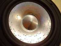
Bud,
My FE206En demonstrates the familiar EnABL "sound-coming-around-the driver" effect. But they still beam noticeably. Would EnABLing the phase plug help?
I thought that the phase plug itself would help HF dispersion. It doesn't (to my ears).
Alan
My FE206En demonstrates the familiar EnABL "sound-coming-around-the driver" effect. But they still beam noticeably. Would EnABLing the phase plug help?
I thought that the phase plug itself would help HF dispersion. It doesn't (to my ears).
Alan
Alan Hope,
EnABL patterns on phase plugs have helped every where I have used them. Dave at Planet 10 knows a lot more about phase plug issues than I do though. To my ears, phase plugs make IM shrieking worse than with a paper voice coil sealing dome and whizzer. This can be dealt with.
Do you have a picture of your application? It is quite likely we can do some things to the whizzer to raise it's effective impedence and perhaps at the same time drop the impedence on the main cone. I do this for the Hemp FR8c driver and now for the Fostex 126 & 127 single cone drivers. Soongsc's mid cone ring, when gotten just right, performs this task very nicely, with perhaps some back side manipulations too.
In any event, I do need to see what you have applied currently, to know what to do next. I do have the Hemps and Lowthers to the point where they do not beam, though only the Lowther PM6A has a phase plug, so I am a little light on experience here
Bud
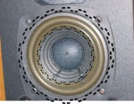
Bud
One of my drivers - nb there is the standard pattern underneath the whizzer too.
EnABLd Fostex
Has a single coat of half-strength micro-gloss.
Generally sounds very good indeed. Well controlled in the Sachikos, and able to confidently cope with awkward stuff like massed choirs. They do not cause listening fatigue.
Strangely the beaming is not totally unpleasant. They sound like slightly different speakers on and off axis, but both listening positions are perfectly enjoyable.
However, less beaming would be good.
Alan
Hi Bud,
For every action there is equal but opposite reaction, this including edge diffraction at a cone edge which cannot fail to generate an axially symmetrical and fractionally time delayed surface wave from the cone edge back radially towards the centre.
When these 'incoming' waves pass over a surface at the centre of the cone, be it a raised dust-cap or phase-plug or open voice-coil pole-face chamber, then there must be yet another reflection or diffraction event.
My thoughts have been checked out by trying different dust caps, with the finding that only a concave dust-cap smoothly allows centrally focussed transverse surface waves to pass through each other 'silently' at the cone centre, as the slightest ring/ridge or even a smooth concave cap sounds as if it is generating increased high frequency output due to on-going drive intermodulating with the previously energised but delayed and concentrically focussed wavefront. The dimension from the centre to edge of a cone also often appears to coincide with a quarter wavelength axial response peak (beaming), this being of different frequency when a phase plug or whizzer is fitted to the same cone, and could thus change a cone's reaction to air-side wave motion.
(The cone edge and centre diffraction-launch/pressure/reflection regions are all places where you find your surface EnABL pattern provides benefit.)
Cheers .......... Graham.
- Home
- Loudspeakers
- Multi-Way
- EnABL - Listening impressions & techniques