@assosman - I have seen this debated on this forum (most recently post 705). I think I have them in the correct orientation, here is my logic.
Capacitor Orientation in Vacuum Tube Circuits
The capacitors should be oriented as follows:
1. Inner foil (start of foil):
- Faces the incoming signal
- Connects to the higher resistance path
- Oriented towards the grid of the vacuum tube
2. Outer foil:
- Faces the outgoing signal
- Connects to the lowest resistance path
- Oriented towards the closest connection to ground
- Aligned with the anode (plate) of the vacuum tube
Audionote caps and VCAPs mark foils differently:
From Audionote website - Caps - the marked line - marks the start of the foil. It is our experience that the Audio Note (UK)™ capacitors perform best when the start of the foil is "facing" the incoming signal.
From VCAP website (the ones I used) - The green (or short lead) lead indicates the outermost foil, and should be connected to the lowest impedance path to ground (Anode or Plate connection). Another way to identify outer foil is the writing on the label flows towards the outer foil.

On the 8900 - grid connection is the front of the board (viewed facing the front plate), so the innermost foil (marked red in the case of VCAP CuTF) should be towards the front) and the writing should be able to be be read front to back (flow of writing to outer foil going to anode (plate) connection).
Capacitor Orientation in Vacuum Tube Circuits
The capacitors should be oriented as follows:
1. Inner foil (start of foil):
- Faces the incoming signal
- Connects to the higher resistance path
- Oriented towards the grid of the vacuum tube
2. Outer foil:
- Faces the outgoing signal
- Connects to the lowest resistance path
- Oriented towards the closest connection to ground
- Aligned with the anode (plate) of the vacuum tube
Audionote caps and VCAPs mark foils differently:
From Audionote website - Caps - the marked line - marks the start of the foil. It is our experience that the Audio Note (UK)™ capacitors perform best when the start of the foil is "facing" the incoming signal.
From VCAP website (the ones I used) - The green (or short lead) lead indicates the outermost foil, and should be connected to the lowest impedance path to ground (Anode or Plate connection). Another way to identify outer foil is the writing on the label flows towards the outer foil.
On the 8900 - grid connection is the front of the board (viewed facing the front plate), so the innermost foil (marked red in the case of VCAP CuTF) should be towards the front) and the writing should be able to be be read front to back (flow of writing to outer foil going to anode (plate) connection).
Hi again, I fitted mine after reading post 705. This is very confusing, can we have an answer for this before my head explodes.
Green to the front or Red to the front
Green to the front or Red to the front
I sent an email to VCAP manufacturer for clarification. I will post his response when/if I hear back from him.
Reply from Chris VenHaus (VCAP) - "The outer foil (green lead on CuTF or short lead on ODAM) is always connected to side of circuit with lowest impedance path to ground. Please see: https://v-cap.com/installation-notes.php."
When I asked "green to anode (plate), red to grid". His response was: "Whatever is lowest impedance path to ground. That can be different based on the circuit, so the best source for that info would be the circuit designer."
So, I believe in most circuits, the anode is the lowest impedance path to ground; so the question is in this 8900 circuit is the anode (plate) the lowest path to ground.????
It took me few years to understand the origination of VCAP.
Green is the outermost foil. I always look at the circuit to apply this rule from vcap.
Green is the outermost foil. I always look at the circuit to apply this rule from vcap.
Feel free to disagree, but the according to the circuit diagram the lower resistance side of the coupling cap is the 12AU7 plate so green (outermost foil) would be to the plate side which would make green on the back and the red VCAP lead to the front.

I agree fully with noob's statement above.
My understanding of this inner outer foil thing is that it could be an issue with noise rejection in some applications, but single ended tube amps are not a concern with noise coming from the capacitor. I opine that you likely cannot hear a difference. However, I have come to accept that there are some in this hobby with super hearing powers that will swear they can hear a difference.
If anyone reverses the orientation, let us know if you could hear a change.
I think I will be getting the soldering iron out tomorrow. I’ll let you know what I think the difference is.
Ohhps! Had an accident and fried one of the A/B power modules this evening. Did something idiotic. Shortened a measure point to ground… Thunder and Lightning!
Swapped the boards and confirmed the problem. When I borrowed a board from my first 8900 everything worked and measured within tolerances so it loks like the board was the only thing destroyed. Now it plays beautiful again. Hurray!
😊
Swapped the boards and confirmed the problem. When I borrowed a board from my first 8900 everything worked and measured within tolerances so it loks like the board was the only thing destroyed. Now it plays beautiful again. Hurray!
😊
"If anyone can interpret the code of this base for date I would appreciate it. I've found that is was 1943 production by some being sold but research is inconclusive. I always thought they were grey plate, but seller with same code had black plate listed. In the right light I would call them black, but doubt it.
Really enjoying the sound. Way more volume than I can get away with living in a condo... maybe not right now, it's happy hour and have it at 2:30."
------------------------------------------------------------------------------------------------------------------------------------------------------------------
When there was rationing going on during WWII there was a Maintenance and Repair program for keeping civilian equipment working stateside. That is the M-R on the base. A K2 code would be 1942. K3 would be 1943. But there can be some overlap too. I have some RCA 6SN7 VT-231 that say May 1943 on the box, but the tubes say K2E. I also have some RCA 2A3 M-R like you but coded V3. Keepers for sure.
Ok. Elekit has shipped me e new one. But for future needs it might be a good idea to fix it. Is the repair done by Elekit? Or where should I send it?you can send the power board for repair
Has anyone one made a switch for NFB on/off to make it possible to change setting with out lifting the lid? Should be an easy mod.
I just installed this switch last week. Very convenient. The is space for the switch to the right of the volume knob when looking at the amp from the front.
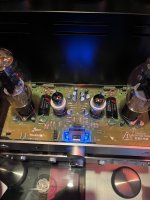
Morning everyone - well, as usual Victor was right about my issue with the LEDs not having equal output and color. One solder joint on a resistor between the LED and the driver tube was bad. Once re-soldered, all is well. LEDs are equal and turn green when they are supposed to and blue when they are supposed to. I have attached the photos of the build and paint job (not perfect, but my second attempt at automotive paint). I think I will settle on using the clear cover Victor sent instead of the solid metal one. Thanks everyone.


